The cable is attached to this connector by placing all conductors in the appropriate
connector cap, and then forcing the connector cap into place.
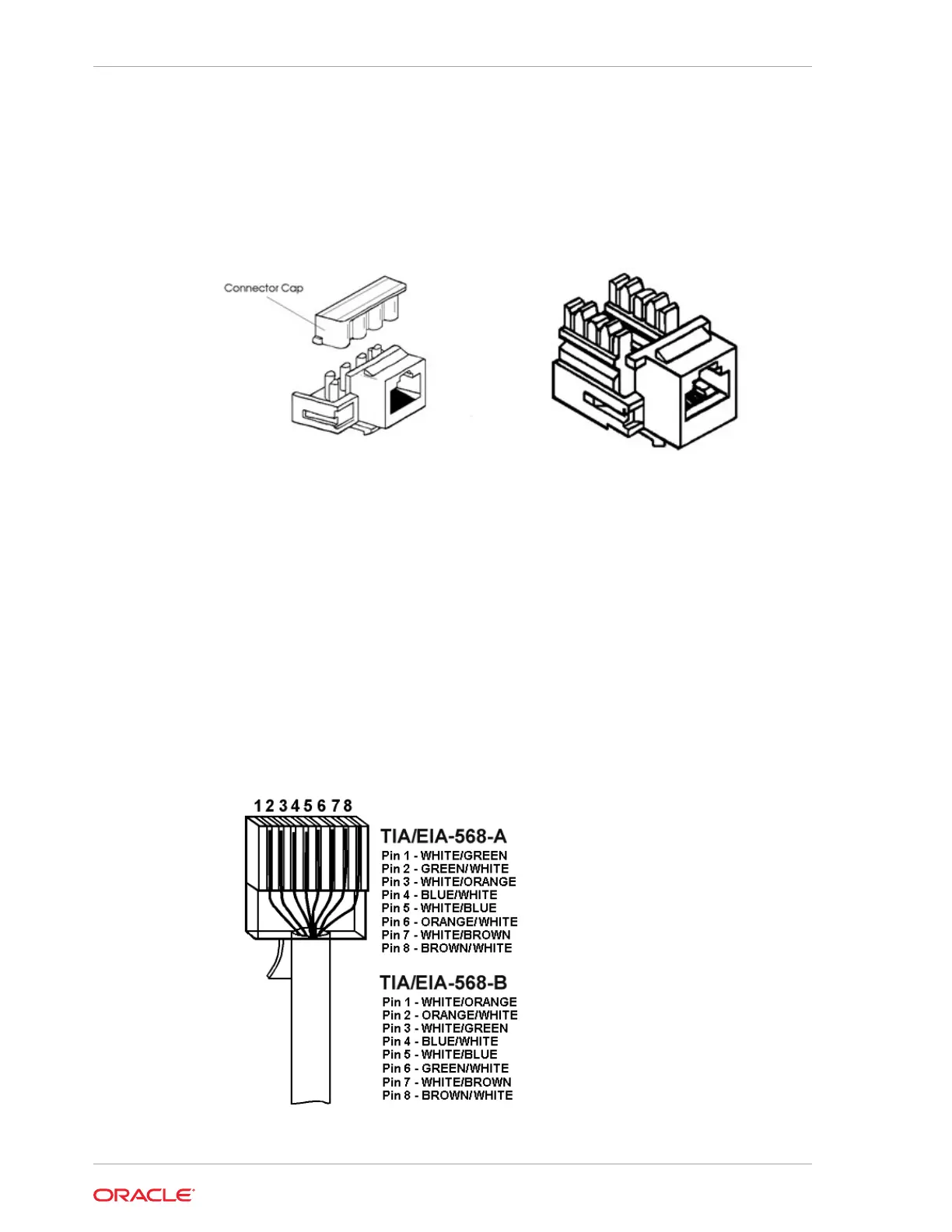
The figure below shows a “keystone” modular jack on the left and a 110 modular
connector on the right.
Figure 27-1 8-Pin Keystone (left) and 110 Connect (right) RJ45 Modular Jack
In addition, there are two methods for terminating the cable. The figures below show
how to terminate cables at the faceplate connectors using the ANSI/TIA/EIA-568-A or
ANSI/TIA/EIA- 568-B cabling standard.
ANSI/TIA/EIA-568-B.1-2001 specifies that horizontal cables are terminated using the
T568A pin/pair assignments, or optionally terminated with the T568B pin pairs to
accommodate certain cabling systems. Mixing T568A terminated horizontal cables
with T568B terminated patch cords (or the reverse) is not recommended.
Please note that pins 1-2, 3-6, 4-5, and 7-8 are +/- signal pairs twisted with each other
within the cable. You must maintain these signal pairs at each end of the cable as well
as the patch cables.
Figure 27-2 Cable Termination
Chapter 27
LAN Cable Termination
27-2
 Loading...