Kitchen Display System Installation
The Kitchen Display System is composed of three components: an Ethernet-based
controller (the Restaurant Display Controller [RDC] or the Kitchen Display Controller
[KDC] 210), LCD monitor, and wired or wireless MICROS bumpbars.
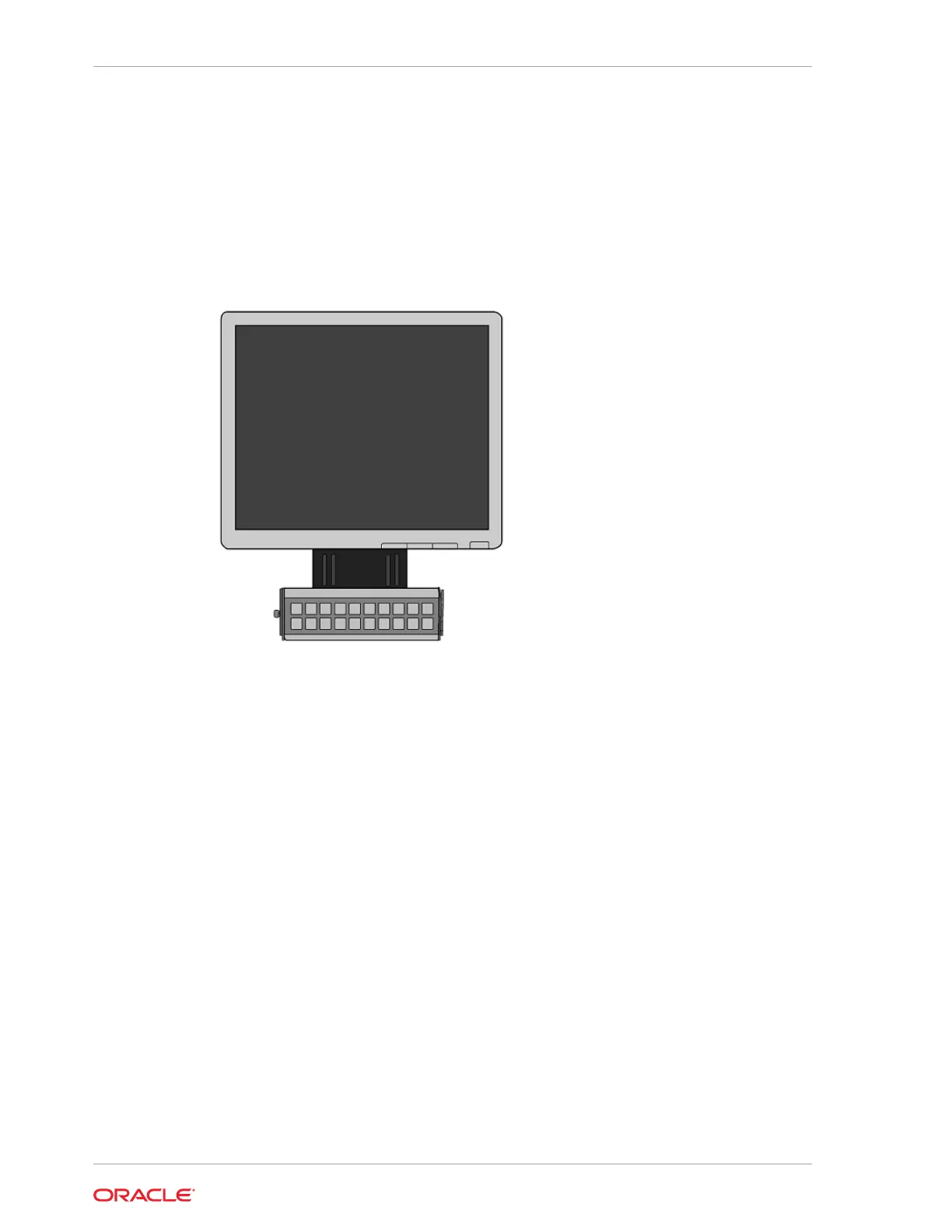
Figure 19-2 Typical KDS Monitor Bumpbar and Mounting Bracket
•
KDS Mounting
• KDS Controllers
• MICROS Wired Bumpbar Installation Considerations
• MICROS Wireless Bumpbar Installation Considerations
KDS Mounting
A wide variety of LCD and bumpbar mounting options are available. Contact your
Oracle MICROS representative if the LCD mounting options need to be determined.
KDS Controllers
KDS Controllers (the Restaurant Display Controller and the Kitchen Display Controller
210) require a Cat 6 faceplate and patch cable near each location. Refer to the Oracle
MICROS Kitchen Display Controller 210 Quick Reference Guide for detailed
information about the KDC 210.
MICROS Wired Bumpbar Installation Considerations
The MICROS Bumpbar MBB-10 and MBB-20 User Guide contains information for
installing the wired bumpbar.
Chapter 19
Kitchen Display System Installation
19-2
 Loading...