Orban 5750 Technical Manual Installation 2-21
There are two tally outputs, which are NPN open-collector and operate with respect to pin 1 (common). Therefore,
the voltage applied to the load (such as a relay or optoisolator) must be positive. You can use the 12 VDC source on
pin 25 to drive the high side of the load, taking into account the fact that the voltage on pin 25 is current limited by
a 310Ω resistor.
The tally outputs are protected against reverse polarity.
• To avoid damaging the 5750, limit the current into a tally output to 30 mA. DO NOT connect a tally output
directly to a low impedance voltage source! The tally outputs are not protected against this abuse and Q3 or Q4
is likely to burn out.
Note that the tally outputs have no special RFI protection. Therefore, it is wise to use shielded cable to make
connections to them.
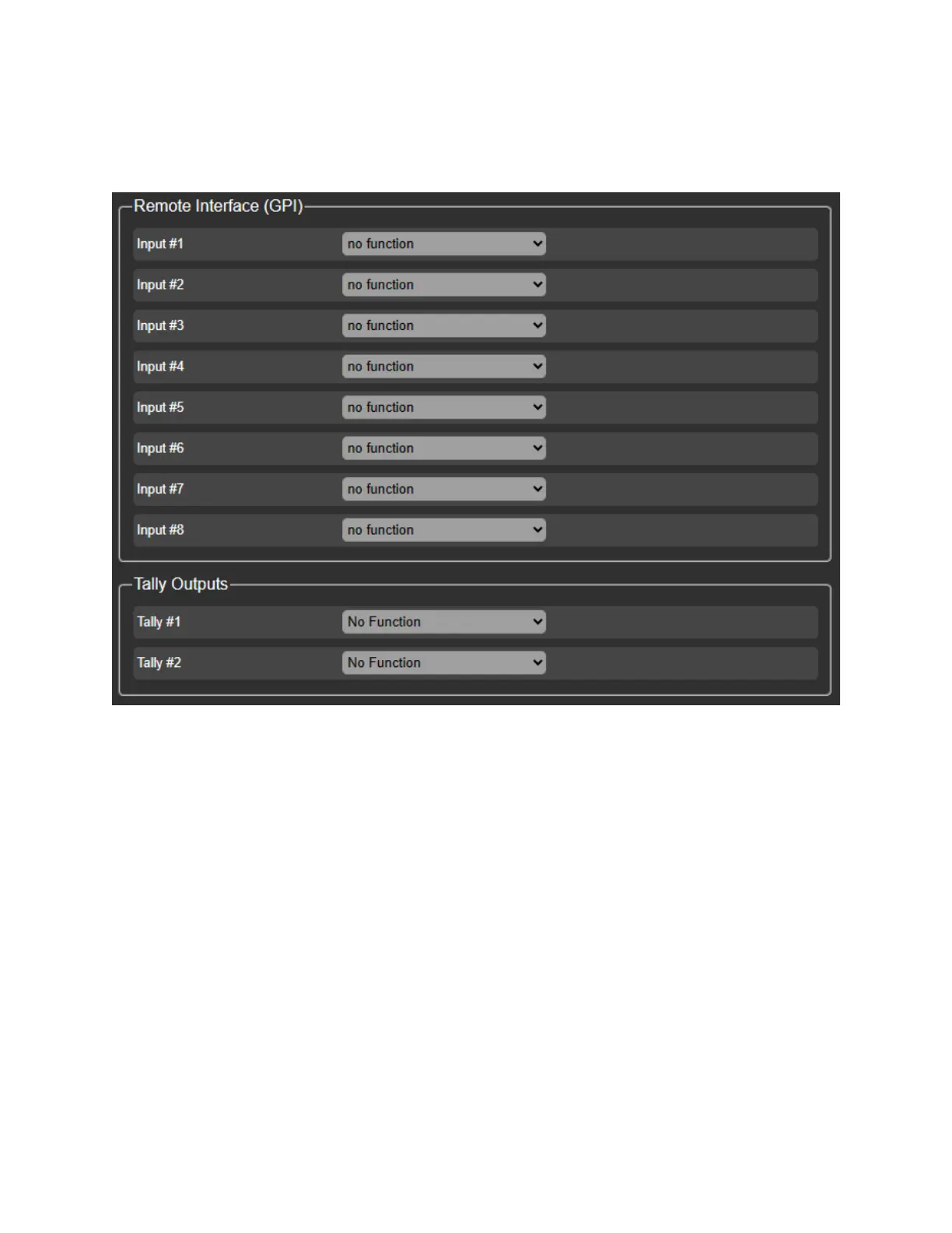
You can program the two tally outputs to indicate a number of different operational and fault conditions.
1) Navigate to the I/O Settings and then REMOTE INTERFACE
• Program the tallys for what you need to switch with the contact closure