2-20 Installation
• In high RF fields, the system is usually grounded through the equipment rack in which the 5750 is mounted. The
rack should be connected to a solid earth ground by a wide copper strap. Wire is completely ineffective at VHF
because of the wire’s self-inductance.
Optically Isolated Remote Control Connections
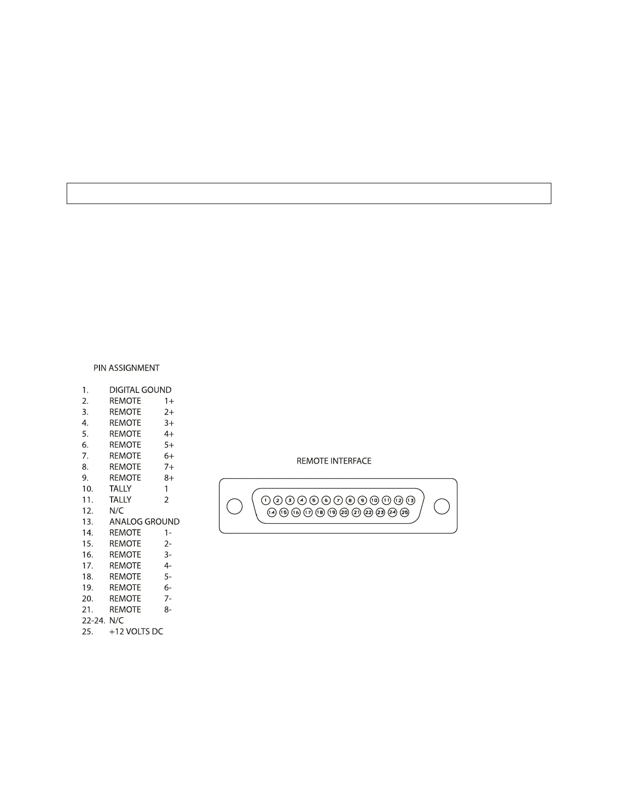
These are terminated in a type DB-25 male connector located on the rear panel. It is wired according to the diagram
below on the following page.
To select the desired function, apply a 5-12V AC or DC pulse between the appropriate Remote Interface terminals.
The (−) terminals can be connected together and then connected to power common at pin 1 to create a Remote
Common. A current limited +12VDC source is available on pin 25. If you use 48V, connect a 2k 10%, 2- watt carbon
composition resistor in series with the Remote Common or the (+) terminal to provide current limiting.
In a high-RF environment, these wires should be short and should be run through foil-shielded cable, with the shield
connected to CHASSIS GROUND at both ends.
Figure 2-1: Wiring the 25-pin Remote Interface Connector