OPTIMOD INSTALLATION
2-21
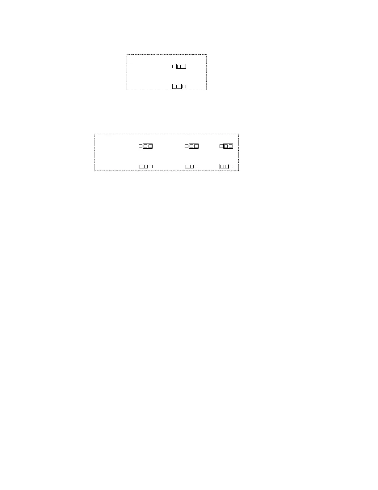
JUMPER JD
FLAT
PRE-EMPHASIZED
Figure 2-10: 4000 Pre-Emphasis Jumper
F)
Set the two channels for stereo coupling.
Place jumpers JG1, JG2, and JG3 in the “COUPLED” position.
JUMPER JG1
JUMPER JG2
JUMPER JG3
COUPLED
INDEPENDENT
Figure 2-11: 4000 Stereo Coupling Jumper
G)
Replace the top and bottom covers.
2. Install the 4000 in the rack. Connect the 4000’s audio input and output.
Refer to the 4000 Operating Manual if you require information about installa-
tion, audio input and output connections to the 4000.
3. Calibrate the 4000’s Output level to the STL.
A) Press both
TONE
buttons on the 4000’s front panel.
B) Adjust the 4000’s Channel A and B
OUT
(Output) levels for 100% peak modula-
tion of the STL.
4. Calibrate the 4000’s Input level for normal operation using tone.
[Skip this step if you wish to calibrate the 4000’s Input level using program
material. (Refer to step 5 on page 2-22.)]
Some facilities have specific standards for transmission line-up. For example,
a transmission standard may state that +4dBu at 400Hz produces 50% modu-
lation of a microwave link. Or PPM6 might allow 8dB of headroom so it
would modulate the link to 40%.
Determine the input level to the studio-to-transmitter link that produces 100%
modulation of the link.
In step 4-(D), we calibrate the gain of the 4000 below the threshold of limit-
ing.
For facilities using VU meters, we suggest:
100% peak level (dBu)–0VU level (dBu)–14db = gain of the 4000