OGi Modem - Hardware Guide
T401, Version .15 14 © ORBCOMM Proprietary
3 Specifications
3.1 Connector
The table below describes the mating connector.
Mini PCI express, 0.8 mm pitch, 52 pin connectors with 26 per side, with
gold plated contacts. Several heights are available from multiple vendors.
TE Connectivity 1775838-2
FCI 10123908
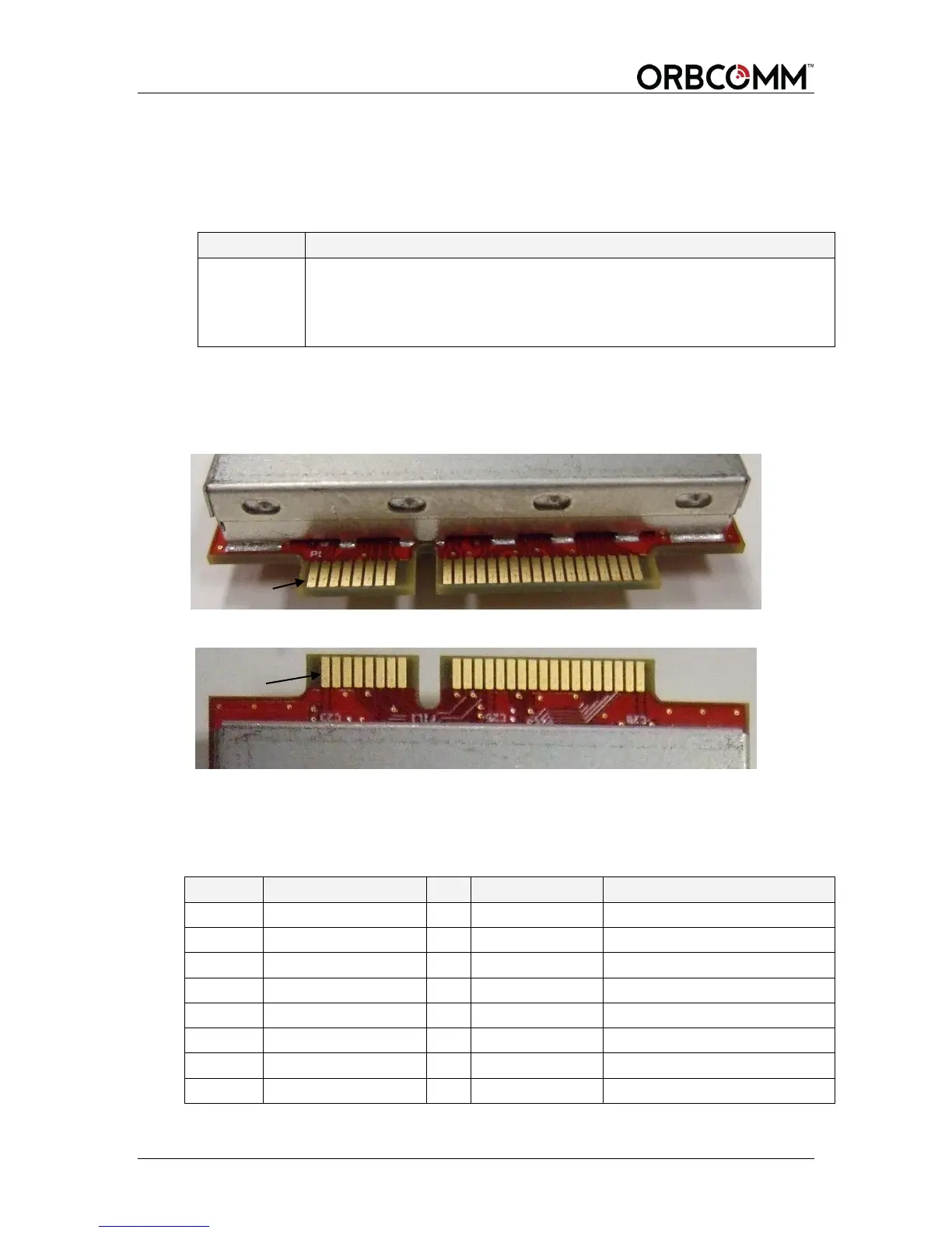
3.1.1 Pin Designations
Figure 7 shows the pin number designations.
Figure 7 Modem Connector Pinout - Top View of Modem (odd numbers)
Figure 8 Modem Connector Pinout - Bottom View of Modem (even numbers)
3.1.2 Pin Descriptions
Table 2 contains the modem pin assignments.
Table 2 Modem Electrical Pin Assignment