OGi Modem - Hardware Guide
© ORBCOMM Proprietary 33 T401, Version .15
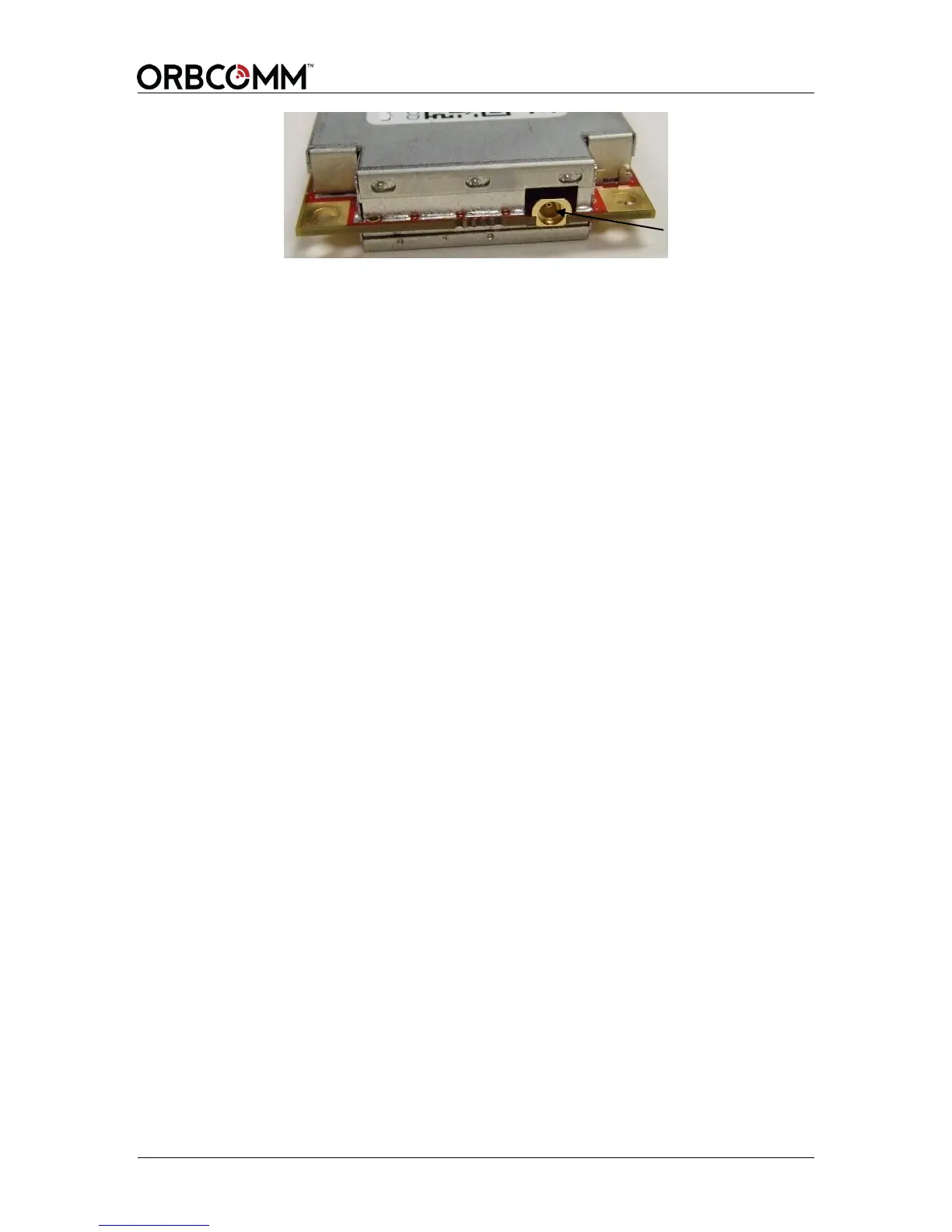
The modem inserts into the connector at an angle, and is held in place with screws and
standoffs that match the connector height. The standoffs and screws generally interface to
a ground connection on the host board. Mounting screws should be properly tightened to
0.80 N-m (7 pound-inches) of torque or as per the specifications of the connector
Manufacturer.
4.7 Unpackaged Antenna Mounting Guidelines
As shown in Figure 17 the unpackaged antenna has a set of four holes sized for M3.5
hardware to secure the antenna to an environmental enclosure surface. A second set of
holes at the corner of the card can be used for mounting with #4 hardware, but the holes
are tight fitting and tolerances need to be considered, so SkyWave recommends the larger
hole set for mounting.