EasyManua.ls Logo

Oriental motor AZD-KD User Manual

Oriental motor AZD-KD
56 pages
To Next Page IconTo Next Page
Page #1 background imageLoading...
Page #1 background image
HM-60315-2
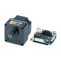
Stepping Motor and Driver Package
AZ
Series/
Motorized actuator equipped with
AZ
Series
DC power input
Built-in controller type
Pulse input type with RS-485 communication interface
Pulse input type
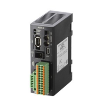
OPERATING MANUAL Driver
MSIP-REM-OMC-088
Thank you for purchasing an Oriental Motor product.
This Manual describes product handling procedures and safety precautions.
Please read it thoroughly to ensure safe operation.
Always keep the manual where it is readily available.
1 Introduction ................................... 2
2 Safety precautions ........................ 5
3 Precautions for use ........................ 7
4 Regulations and standards .......... 8
5 Preparation ..................................... 9
6 Installation ....................................12
7 Connection ...................................14
8 Explanation of I/O signals .......... 25
9 Setting ........................................... 28
10 Guidance ....................................... 32
11 Inspection ..................................... 43
12 Alarm (protective function) .......44
13 Troubleshooting ..........................45
14 To use the product in more
convenient manners ................... 47
15 Accessories.................................... 48

Questions and Answers:

Oriental motor AZD-KD Specifications

General IconGeneral
Output Power15 W, 30 W, 50 W, 100 W, 200 W, 400 W
Protection ClassIP65
Power Supply Voltage200-230VAC
Motor Frame Size60 mm
Voltage200-230VAC

Summary

Safety Precautions for AZ Series Drivers

General Warnings

Critical safety warnings to prevent serious injury or death.

General Cautions

Important cautions to prevent injury or property damage.

Precautions for Use

Driver Installation Guide

Driver Connection Procedures

Connection Method Overview

General illustration and overview of connection procedures.

Power Supply and Grounding

Detailed steps for connecting power and grounding the driver.

Current Sink Output Connection Example

Example wiring for connecting to a current sink output circuit.

Pulse Input Connection Examples

Examples for connecting pulse input signals (line driver & open-collector).

Current Source Output Connection Example

Example wiring for connecting to a current source output circuit.

Pulse Input Connection Examples (Cont.)

Further examples for pulse input connections.

Explanation of I/O Signals

Input Signals Overview

Explanation of the driver's input signals.

Pulse Input Signals (CW/CCW)

Details on CW and CCW pulse inputs for motor control.

Output Signals Overview

Explanation of the driver's output signals.

Setting Driver Functions

Setting for Built-in Controller/RS-485 Types

Configuration steps for specific driver types using switches.

Address Number (Slave Address) Setting

How to set unique slave addresses for RS-485 communication.

Protocol Setting

Configuring the RS-485 communication protocol (Modbus RTU).

Transmission Rate Setting

Setting the communication speed for RS-485.

Setting for Pulse Input Type

Configuration options specific to the pulse input type driver.

Pulse Input Mode Setting

Selecting between 1-pulse and 2-pulse input modes.

Base Current Rate Setting

Adjusting motor current for operating and standstill states.

Guidance on Driver Operation

Home Position Setting Methods

Instructions for setting the motor's home position.

Positioning Operation Steps

Procedures for setting operation data and performing positioning.

High-Speed Return-to-Home Operation

Steps for executing high-speed return-to-home operation.

Driver Inspection and Maintenance

Alarm and Protective Functions

Troubleshooting Common Issues

Related product manuals