5 Installation
−16−
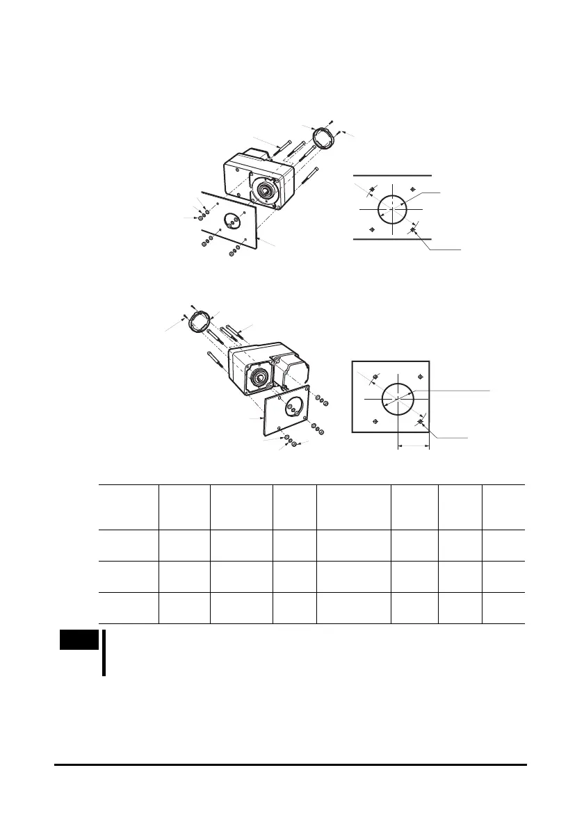
• Using the front side as the mounting surface
When the gearhead is installed by using its front side as the mounting surface, use
the boss of the output shaft to align the center.
Safety cover
Safety cover
mounting screws (M3)
Hexagonal socket head screws
Mounting plate
Washers
Spring washers
Hexagonal nuts
ØB
· Mounting hole dimensions
4×ØC
ØA
• Using the rear side as the mounting surface
Safety cover
Safety cover
mounting screws (M3)
Hexagonal socket head screws
Washers
Hexagonal
nuts
Mounting plate
Spring washers
· Mounting hole dimensions
E
4×ØC
ØD or more
ØA
[Unit: mm (in.)]
Unit
model
Nominal
thread
size
Tightening
torque
ØA ØB ØC ØD E
BLH230 M5
3.8 N·m
(33 lb-in)
70
(2.76)
34
+0.039
0
(1.34
+0.0015
0
)
5.5
(0.217)
25
(0.98)
29
(1.14)
BLH450 M6
6.4 N·m
(56 lb-in)
94
(3.70)
38
+0.039
0
(1.50
+0.0015
0
)
6.5
(0.256)
30
(1.18)
39
(1.54)
BLH5100 M8
15.5 N·m
(137 lb-in)
104
(4.09)
50
+0.039
0
(1.97
+0.0015
0
)
8.5
(0.335)
35
(1.38)
44
(1.73)
Note
When installing the gearhead by using its rear side as the mounting surface,
prevent contact between the mounting plate and motor by keeping dimension
E below the specified value.
 Loading...
