5 Installation
−17−
Maximum applicable plate thickness
Unit model
Maximum applicable
plate thickness
BLH230 5 mm (0.20 in.)
BLH450 8 mm (0.31 in.)
BLH5100 12 mm (0.47 in.)
∗ The figures in the table apply when the supplied hexagonal socket head screw is used.
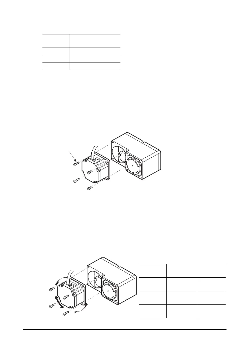
Changing the motor cable’s routing direction
The gearhead can be removed and the motor cable position changed to one of three
90° directions. Note that the motor cable cannot be positioned in the direction where
the cable faces the gearhead output shaft.
1. Remove the hexagonal socket head screws (4 pcs.) attaching the
gearhead and motor and detach the motor from the gearhead.
Hexagonal socket head
screws
2. Using the pilot sections of the motor and gearhead as guides, install the
motor to the gearhead and tighten the hexagonal socket head screws.
At this time, the motor cable position can be changed to one of three 90°
directions.
When installing the gearhead, slowly rotate it clockwise/counterclockwise to
prevent the pinion of the motor output shaft from contacting the side panel or
gear of the gearhead.
Also, confirm that no gaps remain between the motor flange surface and the end
face of the gearhead’s pilot section.
Unit model
Nominal
thread size
Tightening
torque
BLH230 M4
1.8 N·m
(15.9 lb-in)
BLH450 M6
6.4 N·m
(56 lb-in)
BLH5100 M8
15.5 N·m
(137 lb-in)
Change the cable
position to a desired
90° direction.
 Loading...
