Installation
General instructions
IG-136-EN version 10; 23/06/2016
17
cgm.3 system
Fully SF6 gas insulated medium voltage switchgear up to 40.5 kV in accordance with IEC Standards
4 Installation
4.1 Unpacking the equipment
The switchgear of the cgm.3 system is supplied protected
in plastic as standard.
On receiving the equipment, check that the goods supplied
correspond to the order and associated documentation. If
this is not the case, contact Ormazabal immediately.
The disassembly process for the equipment is as follows:
1. Using a blade, cutter or similar tool, cut the cellophane
the cubicle is wrapped in
[6]
.
2. Completely remove the cellophane.
3. Detach the white polystyrene corner pieces.
4. Unscrew the fixings between the base and the pallet.
5. Remove the pallet, handling the cubicle as indicated
in section 2.1.
6. Unpack the accessory box located at the rear or on
top of the cubicle.
7. Remove the self-adhesive protective plastic from the
cable compartment cover.
The self-adhesive plastic must be removed
from the cable compartment cover so that the
equipment enclosure's earth connection may
have the proper electrical continuity.
8. Dispose of any waste in an environmentally-friendly
manner.
It is advisable to make a visual inspection of the equipment
to check whether it has suffered any damage in transit. If
damaged, contact Ormazabal immediately.
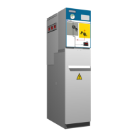
4.2 Location of accessories during transport
A number of accessories are supplied with the cubicles,
located as indicated in the figures below:
Figure 4.1 Location of accessories in cgm.3-p cubicles
[6]
It is advisable to cut the cellophane at the rear of the cubicle or at the corner to avoid scratching the surface.