Installation
General instructions
IG-136-EN version 10; 23/06/2016
19
cgm.3 system
Fully SF6 gas insulated medium voltage switchgear up to 40.5 kV in accordance with IEC Standards
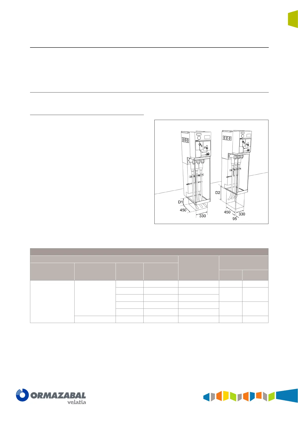
4.4 Recommended cable connection trench
Minimum recommended dimensions based on the trench
dimensions used in the tests in accordance with Standard
IEC 62271-200. In accordance with the radius of curvature
of the cables used, these dimensions may vary
[10]
.
4.4.1 Cubicles with internal arc in gas tank
[8]
up to 20 kA
[9]
- 0.5 s
Feeder function, busbar rise and cable rise
The dimensions of the trench depend on the minimum
radius of curvature of the cables used.
Front and rear
cable input or output
(D1)
Side cable input or
output (D2)
Figure 4.4 Dimensions [mm] of the cable trench for cgm.3-l,
cgm.3-rb and cgm.3-rc
Trench necessary for the feeder, busbar rise and cable rise function
Cable data
Approximate radius
of curvature*
[mm]
Minimum depth
Cable insulation Cable type
Cable section
[mm
2
]
Cable diameter
[mm]
D1 [mm] D2 [mm]
Dry insulation
Single-core 18/30 kV
< 150 41 555 200 500
185 43 590
200 550
240 45.2 640
300 47.5 685
300 660
400 48 745
3-core 18/30 kV < 150 92.7 805 650 650
(*)
Check against the data of the manufacturer of the cable used.
[9]
Tests conducted with a current of 21 kA.
[10]
In each case, bear in mind which cable is to be used in that particular installation.