General Instructions
General description
IG-136-EN version 10; 23/06/2016
8
cgm.3 system
Fully SF6 gas insulated medium voltage switchgear up to 40.5 kV in accordance with IEC Standards
1.3.1 Gas tank
Sealed compartment which houses the busbar and the
switching and breaking elements, where the insulating
medium is SF
6
.
Each gas tank has a pressure relief device to facilitate gas
relief in the event of internal arc.
Thanks to the hermetically-sealed nature of the gas
tank containing all the medium voltage elements, the
equipment is expected to have a minimum service life of
30 years, without replenishing the gas, in accordance with
Standard IEC 62271-1.
Figure 1.2 Gas tank for cgm.3-l
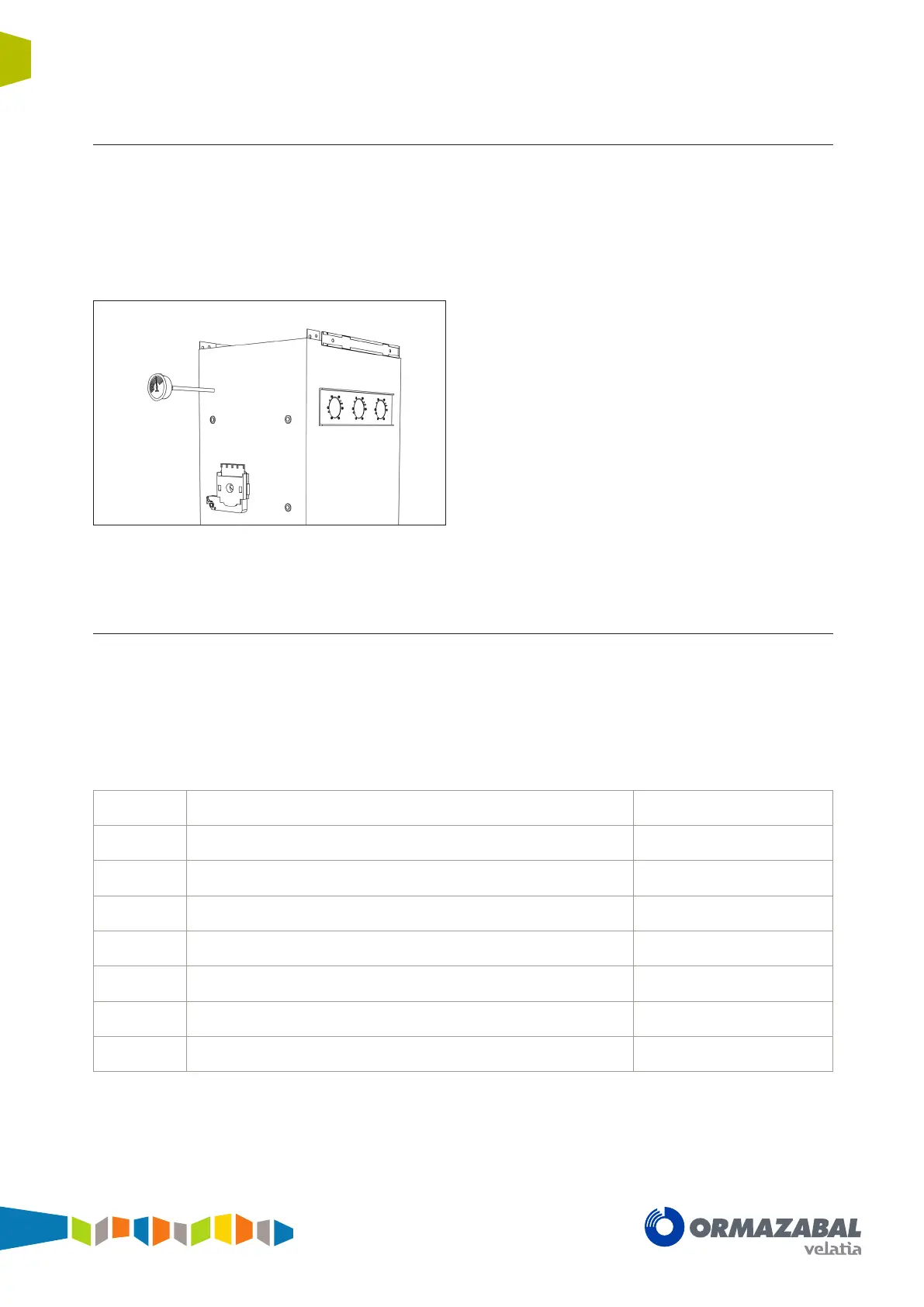
1.3.2 Driving mechanism compartment
This is the compartment in which the switch-disconnector,
earthing switch or circuit-breaker is driven, depending on
the type of function.
The mimic diagram for the main medium voltage circuit is
displayed on the cover of this compartment.
The mimic diagram includes all the position indicators for
the driving elements.
The cgm.3 system has, in line with the cubicle model, the
following types of driving mechanism:
B
Tilting
l, s, s-pt, rb-pt, v, 2lp, 2lv
BM Motorised tilting
l, s, s-pt, 2lp, 2lv
BR-A Accumulation of energy with latch
p, 2lp
BR-AM Accumulation of energy with motorised latch
l, p, 2lp
AV Circuit-breaker without reclosing
v, 2lv
AMV Motorised circuit-breaker without reclosing
v, 2lv
RAV Circuit-breaker with reclosing option
v, 2lv
RAMV Motorised circuit-breaker with reclosing option
v, 2lv
These elements are operated independently, i.e., their
actuation speed does not depend on the speed of the
manual operation.
The B, BM, BR, AR and BR-AM driving mechanisms can
be replaced by upgrading in any of the three possible
positions (closed – opened – earth). Whilst the driving
mechanism is withdrawn, these positions of the switch can
be blocked using a coupling device, whether in service or
not.