General instructions
Recommended sequence of operations
IG-136-EN version 10; 23/06/2016
48
cgm.3 system
Fully SF6 gas insulated medium voltage switchgear up to 40.5 kV in accordance with IEC Standards
5.7 Busbar rise function with earth connection
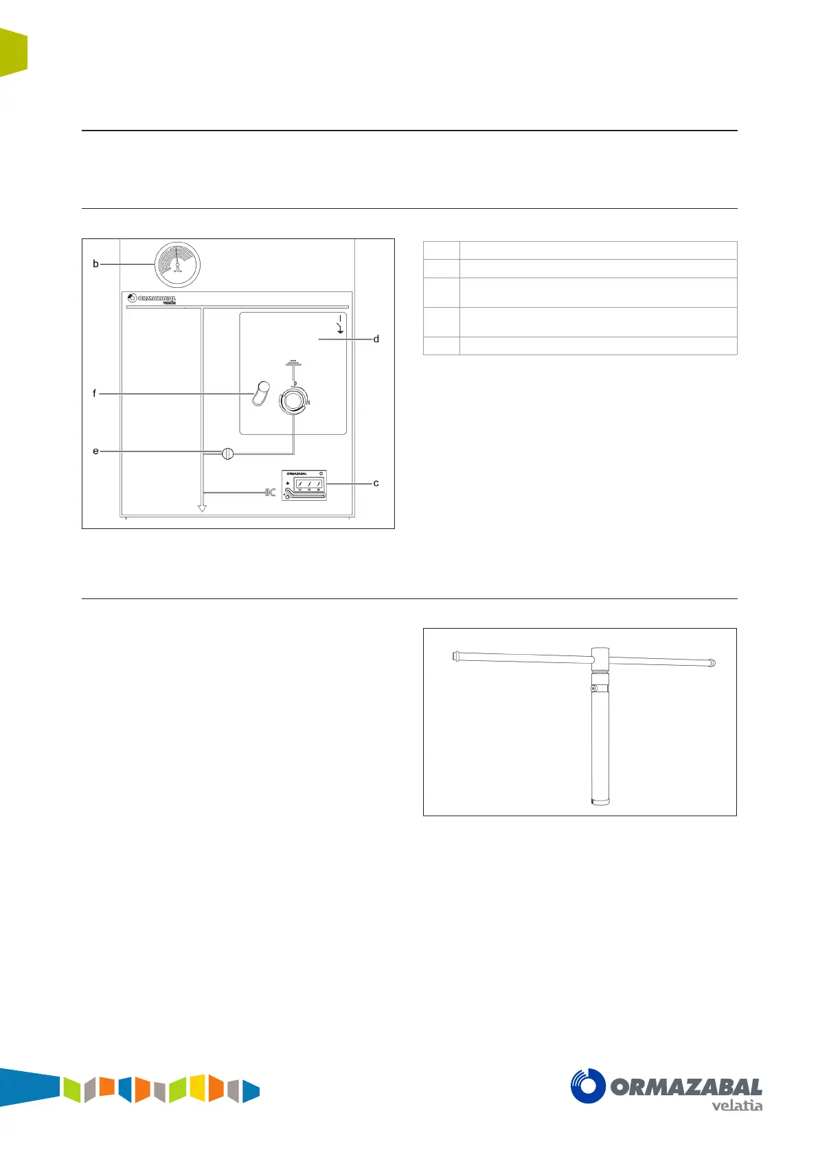
5.7.1 Mimic diagram
b Pressure gauge window
c
Voltage indicator ekor.vpis or ekor.ivds
d
Operation area:
• YELLOW for earthing switch
e
Status indicators
• RED for earthing switch
f Driving shaft access handles
Figure 5.33 Mimic diagram cubicle cgm.3-rb-pt
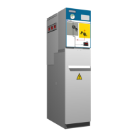
5.7.2 Driving levers
The driving lever to be used to operate the earthing switch
of the busbar riser function with earthing with B driving
mechanisms is:
Figure 5.34 B driving mechanism lever