Installation
General instructions
IG-136-EN version 10; 23/06/2016
31
cgm.3 system
Fully SF6 gas insulated medium voltage switchgear up to 40.5 kV in accordance with IEC Standards
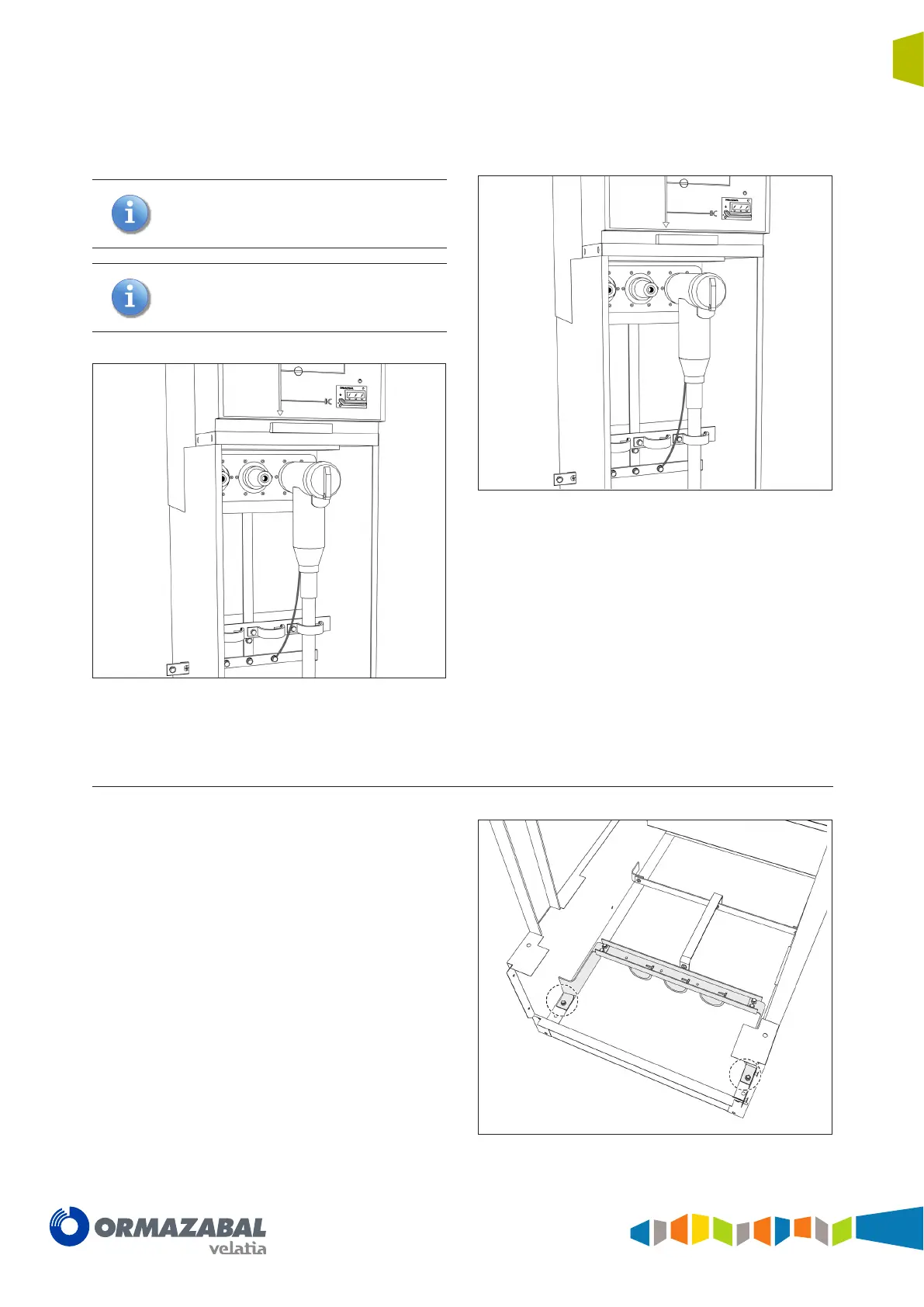
3. Connect the terminals on the front bushings and
secure the cables using the cable support and clamp.
The clamp has two positions, depending on the
cable diameter.
Specic cable supports should be used for
cable diameters above 49 mm. Please check
with Ormazabal.
Figure 4.24 Terminal connection detail
4. Connect the terminal earth braids, if applicable, and
the cable screens.
Figure 4.25 Horizontal front connection process
5. Put the cable compartment cover back in place.
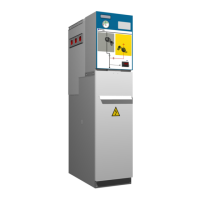
4.8.2 Cable connection in fuse protection function 1400 mm high
The cable support in fuse protection functions, measuring
1400 high, is supplied secured to the base with two M8
screws and nuts, as shown in Figure 4.26
Figure 4.26 Cable support in transport position