General instructions
Recommended sequence of operations
IG-136-EN version 10; 23/06/2016
46
cgm.3 system
Fully SF6 gas insulated medium voltage switchgear up to 40.5 kV in accordance with IEC Standards
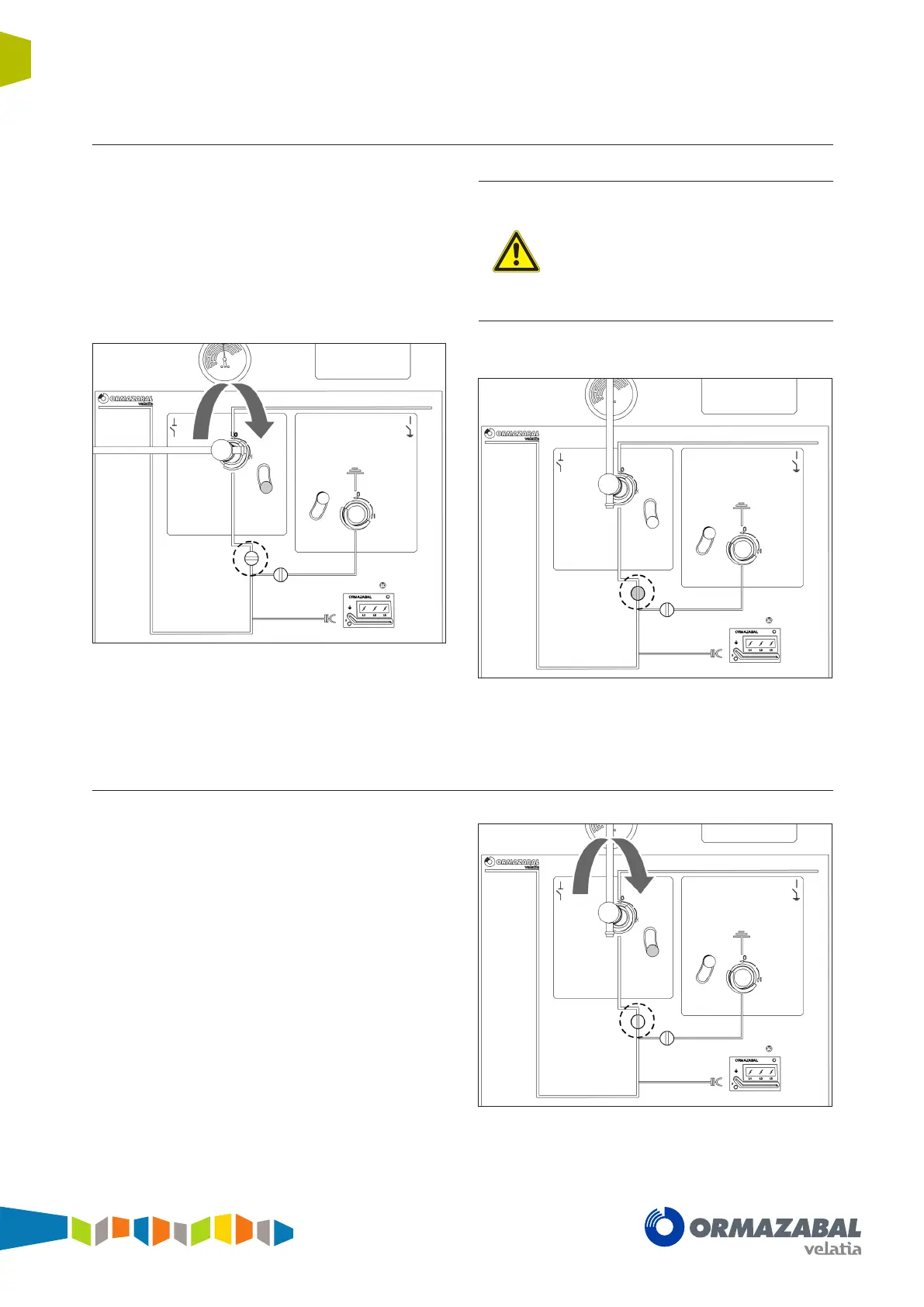
5.6.4 Connection of the switch-disconnector from the disconnected position
1. Move the driving shaft access handle in the grey zone
to its lower position.
2. Connection operation:
a) Manual operation (B driving mechanism). Insert
the lever in the switch access (grey area), move
the driving arm to the end and turn clockwise 90º.
Figure 5.27 Lever turn process
b) Motorised operation (BM driving mechanism).
Activate the corresponding operation command.
When, for any reason, the motor stops
halfway through a motorised operation,
before restarting it you must nish the
operation manually, so that the whole
mechanism: sensors, controllers, etc., are in
a reliable, effective and logical position for the
control system of the motorised unit when it is
switched back on.
3. Verify that the cubicle is in disconnected position.
Figure 5.28 Switch-disconnector closed
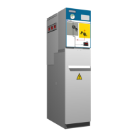
5.6.5 Opening operation from closed position
1. Move the driving shaft access handle in the grey zone
to its lower position.
2. Disconnecting operation:
a) Manual operation (B driving mechanism). Insert
the lever in the switch access (grey area), move
the driving arm to the end and turn anti-clockwise
90º.
Figure 5.29 Lever turn process