General description
General Instructions
IG-136-EN version 10; 23/06/2016
9
cgm.3 system
Fully SF6 gas insulated medium voltage switchgear up to 40.5 kV in accordance with IEC Standards
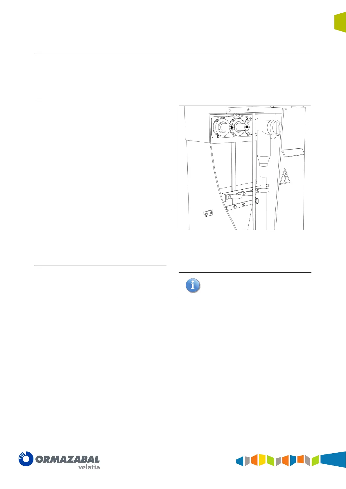
1.3.3 Base
Made up of the cable compartment and the gas relief
compartment:
Cable compartment
This is located in the lower front section of the cubicle
and has a cover interlocked with the earthing switch, thus
allowing front access to the medium voltage cables.
As standard, designed to contain up to:
• Two shielded screw-in terminals (reduced)
per phase or one terminal (reduced) plus
surge arrester (reduced) with space for the
corresponding incoming power cables.
• Cable ties for the power cables.
• Earthing bars.
As an option:
• Two symmetric terminals or symmetric terminal
plus symmetric surge arrester.
• Metallic voltage transformers.
Figure 1.3 Cable compartment
Gas relief compartment
The cgm.3 system by Ormazabal is designed and
constructed to withstand at least the thermal and dynamic
effects of an arc of 16 kA for 0.5 seconds should a defect
result in an internal arc in the gas compartment. The
system conducts the gases generated in a fully controlled
manner to avoid any possible injury to people in the
equipment operation area.
Optionally, a chimney can be positioned in the
rear of the cubicle to redirect the gases to the
top section. Please check with Ormazabal.