General instructions
IG-136-EN version 10; 23/06/2016
4
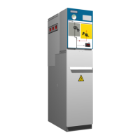
cgm.3 system
Fully SF6 gas insulated medium voltage switchgear up to 40.5 kV in accordance with IEC Standards
5 Recommended sequence of operations ....................................... 34
5.1 Checking the gas pressure ...............................................................34
5.2 Voltage presence indicator ...............................................................34
5.3 Phase balance check ....................................................................35
5.4 Feeder function .........................................................................36
5.4.1 Mimic diagram ....................................................................36
5.4.2 Driving levers .....................................................................37
5.4.3 Opening operation from earthing position ...............................................37
5.4.4 Switch closing operation from the disconnected position ...................................38
5.4.5 Opening operation from closed position ................................................39
5.4.6 Earthing operation from the disconnected position ........................................40
5.4.7 Cable test........................................................................40
5.5 Busbar switch function ..................................................................41
5.5.1 Mimic diagram ....................................................................41
5.5.2 Driving lever......................................................................41
5.5.3 Switch closing operation from the disconnected position ...................................42
5.5.4 Opening operation from closed position ................................................43
5.6 Busbar switch function with earth connection ...............................................44
5.6.1 Mimic diagram ....................................................................44
5.6.2 Driving lever......................................................................44
5.6.3 Opening operation from earthing position ...............................................45
5.6.4 Connection of the switch-disconnector from the disconnected position ........................46
5.6.5 Opening operation from closed position ................................................46
5.6.6 Earthing operation from open position..................................................47
5.7 Busbar rise function with earth connection..................................................48
5.7.1 Mimic diagram ....................................................................48
5.7.2 Driving levers .....................................................................48
5.7.3 Earthing switch disconnection ........................................................49
5.7.4 Earthing switch connection ..........................................................49
5.8 Fuse protection function .................................................................51
5.8.1 Mimic diagram ....................................................................51
5.8.2 Driving lever......................................................................51
5.8.3 Opening operation from earthing position ...............................................52
5.8.4 Spring charge operation and closing of the switch - disconnector from disconnected position.......52
5.8.5 Opening operation from the switch-disconnector closed position .............................53
5.8.6 Earthing operation from the open position...............................................54
5.9 Fuse replacement sequence ..............................................................54
5.9.1 Selection of recommended fuses .....................................................57