Recommended sequence of operations
General instructions
IG-136-EN version 10; 23/06/2016
55
cgm.3 system
Fully SF6 gas insulated medium voltage switchgear up to 40.5 kV in accordance with IEC Standards
As an option, an auxiliary blown fuse indication
for any of the three fuses is also available.
More precisely, it consists of a normally
open contact and a normally closed contact
(1NO + 1NC) for auxiliary circuits such as an
illuminated indication showing that any of the
fuses has blown.
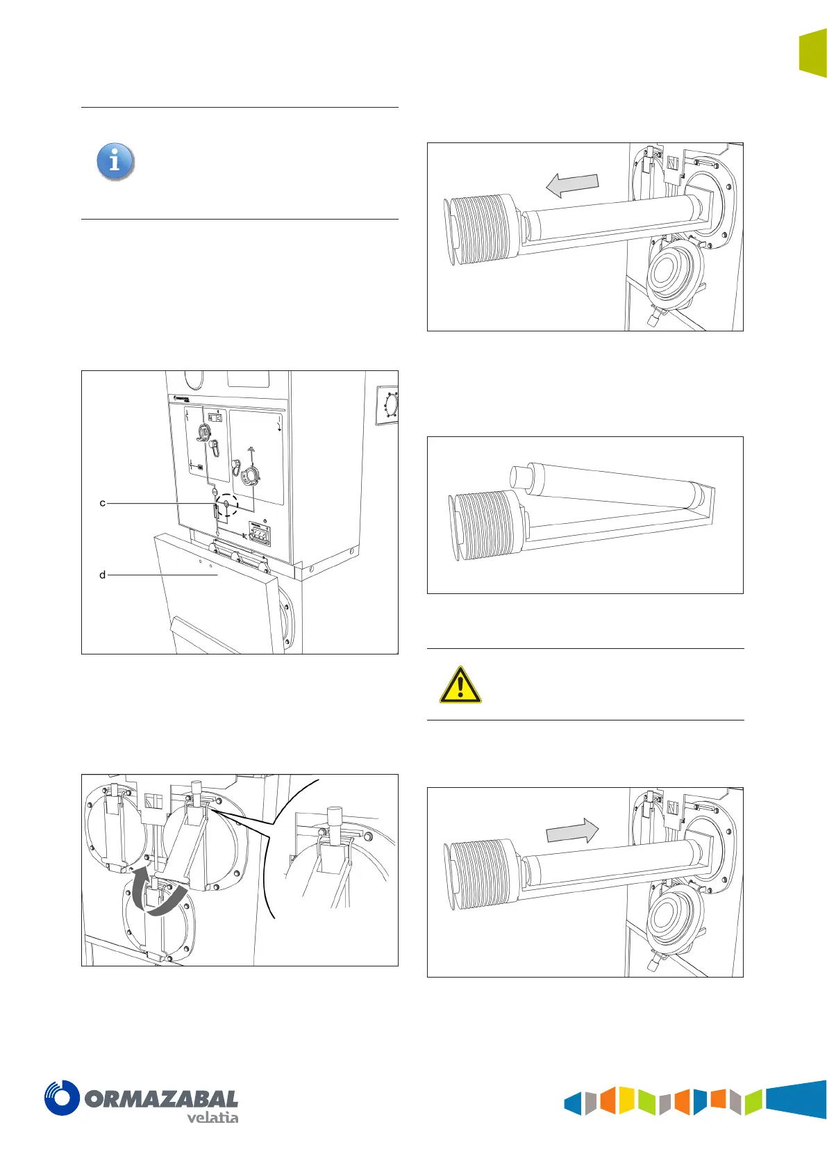
In order to replace the fuses, the following procedures
must be followed:
1. Close the earthing switch (c).
2. Remove the cable and fuse compartment access
cover by pulling the handle (d) up.
Figure 5.50 Cable and fuse compartment cover opening
3. Pull up the handle on the fuse holder cover until
the locking clip is unhooked and then pull sharply
outwards to open the fuse holder.
Figure 5.51 Fuse-holder opening
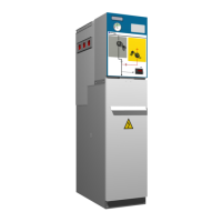
4. Remove the fuse holder carriage by pulling it outward.
Figure 5.52 Removing the fuse holder carriage
5. Replace the blown fuse, taking special care with the
striker as shown in the figure.
Figure 5.53 Replacing the medium voltage fuse
Make sure that the end of the new fuse with
the striker faces the carriage insulator end. It
is advisable to change all three fuses, even
if only one of them appears to be damaged.
6. Insert the fuse holder carriage in its compartment by
pulling it inward.
Figure 5.54 Inserting the fuse holder carriage