IG-123-EN version 11; 23/07/2021
37
General instructions
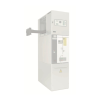
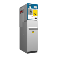
cpg.0: GIS medium-voltage switchgear,
gas insulated, up to 40.5 kV,
in accordance with IEC Standard
Installation
CAREFUL, INSTALLER!
Follow the recommendations below when designing the
part of the ducts NOT included in Ormazabal's scope of
supply:
1. The ducts must exit to an adjacent room or to outside
the room where the cubicles are installed.
2. The area dened by the installer as the termination of
the gas duct must be a safe area: the discharged gases
must not aect or damage people and/or equipment.
3. The ducts must be made of galvanised steel
DX51D+Z275 according to EN 10346 or similar.
4. The duct must be at least 1.2 mm thick throughout its
length.
5. The gas passage section must always respect at least
the dimensions of the passage section of Figure 6.20:
150,000 mm
2
.
6. Whenever the ducts are designed in parts:
a. The joints are made with M8 bolts.
b. The duct sections are joined by connecting anges,
in addition to the lugs tted for this purpose (6 in
each joint) (Figure 6.21).
c. Ceramic type sealing joints are used to prevent leaks
at the joints between the dierent duct sections
(4 x 18 mm ceramic strip) (Figure 6.22).
d. Seal any gaps in the duct with a single-component
polyurethane sealant.
7. If the ducts require a curved section, at least the rst
750 mm must be straight before making any change
of direction. The section must remain unchanged
throughout.
8. For gas discharge to the outside, it is recommended to
direct the gases horizontally or upwards at an angle of
45° to the horizontal to prevent the ingress of rainwater,
dirt, etc. and ensure the gases are not directed towards
a working area.
9. The recommended length for the pipe is between
1 and 2 m. For other dimensions, contact Ormazabal.
10. The switchgear with gas ducts solution is tested in
accordance with IEC 62271-200: 2011 and minimum
installation distances to walls and ceilings are as shown
in Figure 6.1 and Table 6.1.
11. When assembling a "High Cube" type container, the
container must have a removable roof or access to the
top part of the busbars in order to carry out assembly
and work.
Figure 6.20. Minimum gas passage section dimensions
Figure 6.21. Lugs to join the duct sections
Figure 6.22. Ceramic type sealing joints (4 x 18 mm)