IG-123-EN version 11; 23/07/2021
30
Installation General instructions
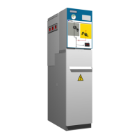
cpg.0: GIS medium-voltage switchgear,
gas insulated, up to 40.5 kV,
in accordance with IEC Standard
6.8. Cable connection
The cables are connected to the bushings with IEC type
reinforced connection connectors (screwable).
Never touch live connectors, not even screened
connectors. Screening does not constitute protection
against direct contact.
When the equipment is in service and a back-up cubicle
is left with voltage in the upper busbar and without
cables in the bottom bushings, insulating plugs must
be placed on the bushings or the disconnector must be
placed in earthing position, and locked in its position
with a padlock.
The recommended connectors are detailed below.
Cubicle
model
Manu-
facturer
Connector
Connector
series
Nº
terminals
Terminal
conguration
Max. rated
current
connector
[A]
Total
connector
length
[mm]
Max. diameter
on insulation
admitted by
the connector
[mm]
cpg.0-v 24 kV
25 kA 630 A
Nexans
EUROMOLD
Screened
400TB 1 cable 400TB + CUP 800 255 37.5
440TB 1 cable 440TB + CUP 1250 255 56
480TB
1 cable 480TB + CUP 1250 185 40.5
1 cable + SA 480TB + 800SA + CUP 1250 290 40.5
484TB
1 cable 484TB + CUP 1250 185 56
1 cable + SA 484TB + 800SA + CUP 1250 290 56
Continued on next page