IG-123-EN version 11; 23/07/2021
3
General instructions
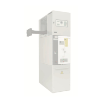
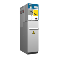
cpg.0: GIS medium-voltage switchgear,
gas insulated, up to 40.5 kV,
in accordance with IEC Standard
Contents
Contents
1. General description ...................................................4
1.1. Models ......................................4
1.2. Standards applied............................4
1.3. Main components ...........................5
2. Technical characteristics..........................................12
2.1. Electrical characteristics .....................12
2.1.1. Name plate .................................14
2.2. Mechanical ratings ..........................15
2.2.1. Dimensions.................................15
2.3. IP rating ....................................16
3. Normal service conditions
(a)
....................................17
4. Handling and transport ...........................................18
4.1. Transport conditions ........................18
4.2. Lifting means ...............................18
5. Storage ......................................................................20
6. Installation ...............................................................21
6.1. Unpacking the equipment ..................21
6.2. List of assembly materials supplied ..........21
6.3. Minimum installation distances..............22
6.4. Cable connection trench ....................22
6.4.1. Recommended dimensions .................23
6.5. Fixing to floor...............................23
6.6. Joining the cubicles .........................24
6.6.1. cpg.0-v 24 kV 630 A .........................25
6.6.2. cpg.0-v 1250 A and 1600 A/cpg.0-pt/
cpg.0-vl. ....................................25
6.6.3. cpg.0-v 2500 A..............................26
6.6.4. cpg.0-c .....................................26
6.6.5. cpg.0-s .....................................27
6.6.6. cpg.0-f/cpg.0-fl .............................27
6.6.7. cpg.0-rb . . . . . . . . . . . . . . . . . . . . . . . . . . . . . . . . . . . .28
6.7. Equipment earthing ........................29
6.8. Cable connection ...........................30
6.9. Installing the gas duct to outside the cubicle
room .......................................36
7. Operations sequence ...............................................38
7.1. Operating and commissioning sequence ....38
7.1.1. Disconnector function operating sequence
(cpg.0-s) ....................................38
7.1.2. Circuit-breaker operating sequence
(cpg.0-v/cpg.0-vl)...........................44
7.1.3. Busbar coupling function operating
sequence (cpg.0-c)..........................55
7.1.4. Busbar riser cubicle (cpg.0-rb) ...............60
7.1.5. Busbar earthing operating sequence
(cpg.0-pt)...................................60
7.1.6. Fuse protection operating sequence
(cpg.0-f/cpg.0-fl)............................63
8. Safety elements ........................................................73
8.1. ekor.ivds voltage detectors .................73
8.2. Locking with padlock .......................73
8.2.1. Locking with key lock .......................73
8.3. Interlocks ...................................74
9. Maintenance .............................................................75
9.1. Voltage indicator test .......................75
9.2. Preventive maintenance of circuit-breakers ..75
10. Spares and accessories ............................................76
11. Environmental information ....................................77
11.1. Sulphur hexafluoride SF
6
....................77
11.2. Recyclability ................................77