ORTEA SpA MAT200 aug21
10 / 24
VARIATION RANGE MEANS CHANGING THE UNIT RATED POWER AS WELL. THE TWO RANGES ARE ALTERNATIVE TO EACH
OTHER AND MUST NOT BE CONNECTED CONTEMPORARILY.
WARNING BE SURE THAT PHASE AND NEUTRAL WIRES ARE CONNECTED TO THE RELEVANT TERMINALS. SWAPPING THE
INPUT CONNECTION WITH THE OUTPUT ONE COULD CAUSE SERIOUS DAMAGE.
Check the tightness of the connections and carefully close the cabinet.
6.3 START-UP
Before starting-up,it is recommendable tocheck whether haulage and long permanence in a warehouse might have affected
the unit.If clear signs of dust,dirt or rust can be detected, follow the instruction given in the Maintenance chapter concerning
how to clean the components. Supply the rated voltage. Power circuit, auxiliary circuits, control card and Input/Output digital
analysers are energised. The input and output values can now be read on the instruments: check that they comply with the
rated ones. The equipment is now ready for use. Connect the load and check on the analyser that the output voltage
regulation is steady and that the circulating currents do not exceed the rated values.
6.4 SETTINGS
DANGER DANGEROUS VOLTAGE IS PRESENT INSIDE THE STABILISER AND THE CONTROL CARD. FOR THIS REASON, ONLY
TRAINED AND QUALIFIED PERSONNEL AWARE OF THE INVOLVED RISKS MUST PERFORM THE DESCRIBED SETTINGS. SETTING
OPERATION MUST BE PERFORMED ONLY IF STRICTLY NECESSARY. SUITABLE TOOLS AND PROTECTIVE MEANS MUST BE USED
WHEN PERFORMING THE DESCRIBED ACTIVITIES. READ THIS HANDBOOK COMPLETELY BEFORE STARTING ANY
INTERVENTION ON THE UNIT OR THE CONTROL CARD.
Note For a complete reset, the unit must have been switched off for at least five minutes.
6.4.1 Trimmers
The trimmers are set during the testing session and it is strongly recommended NOT to alter such settings. In case of doubt,
please refer to an authorised Service Centre.
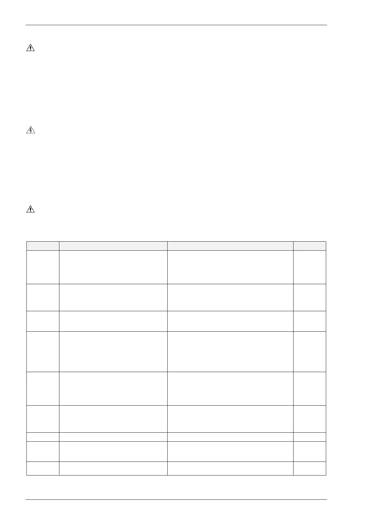
6.4.2 Dip switches
WARNING SW1 (DIP 1-2) CAN BE USED ONLY IF THE UNIT NOMINAL VOLTAGE IS ONE AMONG 360V, 380V, 400V OR
415V (RESPECTIVELY CORRESPONDING TO 210V, 220V, 230V AND 240V PHASE-TO-NEUTRAL VOLTAGE). IF THE
NOMINAL VOLTAGE IS DIFFERENT, SW1 SETTING MUST NOT BE ALTERED AND THE TARGET VOLTAGE AMENDMENT MUST BE
CARRIED OUT VIA SOFTWARE.
REF. PARAMETRE POSITION DEFAULT
SW1 DIP1
SW1 DIP2
Selection of the voltage to be stabilised.
If the voltage is set via software, the dip-
switched are disabled
OFF OFF 210
ON OFF 220
OFF ON 230
ON ON 240
DIP1=OFF
DIP2=ON
SW1 DIP3
Enabling of each motor regulation by
means of external potentiometers.
The full-scale value is set with the
software
ON = enabled
OFF = disabled
OFF
SW1 DIP4
Acoustic alarms disabling.
Internal buzzer and external siren are cut
off
ON = acoustic alarms off
OFF = acoustic alarms on
OFF
SW1 DIP5
SW1 DIP6
Roller saving function regulation
OFF OFF Fast regulation (more movements)
ON OFF Fast intermediate
OFF ON Slow intermediate
ON ON Slow regulation 8fewer
movements)
OFF
SW2 DIP7
Minimum regulation enabling.
Activates the voltage resetting to the
minimum value in case of blackout (even
only on one phase ) or following the
ALL_PHASE_LOSS alarm
ON = enabled
OFF = disabled
ON
SW2 DIP8
Min/max voltage alarm enabling.
Enables the generation of an alarm in
case the output voltage is out of range for
a set time.
ON = enabled
OFF = disabled
ON
SW2 DIP9 DO NOT ALTER OFF OFF
SW2 DIP10
Automatic reset of stored alarms. When
enabled, the alarm reset occurs 180 secs
after it has disappeared
ON = enables automatic reset
OFF = manual reset (push-button)
OFF
SW2 DIP11 Manual bypass command
ON = manual bypass activation
OFF = normal operation
OFF