ORTEA SpA MAT200 aug21
8 / 24
5 STABILISER DESCRIPTION
Please refer to the attached Data Sheet for a complete list of the technical characteristics.
This handbook deals only with the standard units. If optional devices such as by-pass switch, circuit breakers, etc. are
provided, please refer to the attached relevant technical sheets.
The units, designed and built in compliance with the European Directives concerning CE marking (Low Voltage Directive and
Electromagnetic Compatibility Directive), can be used in both A and B environments according to EN61439-1/2 and are
supposed to be connected between mains and user. The main features are:
use with asymmetrical input supply and single-phase loads or unbalanced three-phase loads;
operation based on the ‘rms voltage’ and not on the average one. This type of control can supply the load a correctly
stabilised voltage even with non-sinusoidal waves;
regulation performed independently on each single phase (referring to the neutral, which must be available and
connected;
fully functioning with load charge variable from 0 to 100% and 100% phase unbalance.
up to 30% harmonic content admitted on the load current. With higher percentage, nominal power must be de-rated.
insensitivity to the load power factor
absence of generation of noticeable harmonic distortions in the output voltage.
5.1 MAIN COMPONENTS AND WORKING PRINCIPLE
The main components are:
three-phase ‘buck/boost’ transformer
motorised three-phase autotransformer (or 3 single-phase ones) with continuously variable transformer ratio (voltage
regulator)
electronic control card which runs the system in terms of regulation and alarm management.
electronic signalling card (connected to the control card)
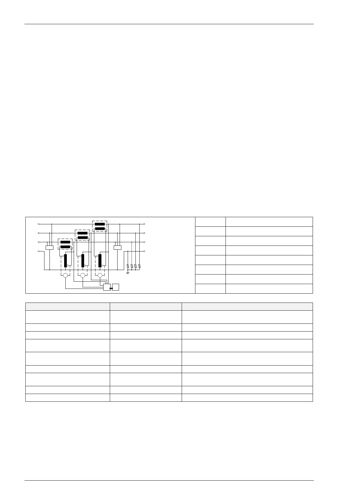
A representation of the system is shown in the picture below. The control circuit compares the output voltage value to the
adjusted one. When the percentage variation is too high, the control drives the voltage regulator motor. By doing so the
regulator rollers change their position thus varying the voltage drawn and supplied to the buck/boost transformer primary
winding. Being the secondary voltage of the buck/boost transformer in phase or in opposition to the supply, the voltage
drawn from the regulator is added or subtracted to the mains voltage, thus compensating its variations
PVI Input digital multimetre
TM Buck/boost transformer
VT Voltage regulator
M DC motor
N1 Control card
N2 LED card
PVO Output digital multimetre
SA2 Class II SPD
5.2 PROTECTIONS
PROTECTION IN CASE OF ACHIEVED THROUGH
OLTAGE RESET TO THE MINIMUM
VALUE
Black-out
mounted on the control card
MOTOR ROTATION STOP Motor overloaded Control card
MOTOR ROTATION STOP Motor short-circuit Control card
VERLOAD ON THE VOLTAGE
REGULATOR
Excessive current flowing
through the regulator
While the protection is active, the red
alarm LED 'Stabilisation off' on the front panel is on.
EGULATOR ROLLERS
OVERTEMPERATURE
Overheating
Thermal probe on the central roller of each roller
group.
ROOF FANS ACTIVATION T ambient > 35°C Adjustable thermostat
OLTMETER LINES AND MOTOR
SUPPLYING CIRCUITS
Circuit overload Fuses
CONTROL CARD PROTECTION Card overload Two 5x20 10A delayed fuses
OVERVOLTAGE Transients & spikes Output Class II SPDs
The intervention of any of the above mentioned protections (except for the fuses) is signalled by luminous and acoustic
alarms. One or more lamps installed inside the enclosure switch on when the door supporting the control panel is open.
5.2.1 Regulator overcurrent protection
The protection is automatically controlled by the control card which intervenes when the regulator rollers are overcharged
by a high current. When this situation is detected, the control card drives the regulator rollers to a safe position.
If the input voltage is lower than the target output voltage, the latter coincides with the input voltage. If the input voltage is
higher than the target output voltage, the latter coincides with the target voltage. When the alarm condition stops, the unit
goes back automatically to the regular working mode. In case of control card failure, the regulator rollers are driven to the
minimum output voltage position. The output voltage shall be decreased (in relation to the input voltage) of the maximum
percentage allowed for by the nominal data.
TM
SA2
TM
N2
N
N1
OUTPUT
W1 W3
V1 V2
INPUT
N
U1 U2
PVO
M
PVI
M
VT VT VT
TM
M