ORTEA SpA MAT200 aug21
17 / 24
8.4.2 B – phase LEDs
The phase indications provided are listed in the table below (starting from the top one):
POSITION COLOUR FUNCTION
1 Blinking green Card supplied and functioning
2 red Increase limit switch
3 yellow DC motor in increasing mode
4 yellow DC motor in decreasing mode
5 red Decrease limit switch
8.4.3 C– alarm LEDs
Positioned on the right side of the phase signals, the alarm LEDs indicate a malfunctioning situation. Any abnormal condition
generates an acoustic alarm as well. The alarm indications provided are listed in the table below (starting from the top one):
POSITION FUNCTION
1 Output voltage below the set minimum threshold
2 Output voltage above the set maximum threshold
3 Output current above the set maximum threshold
4 Stabilisation OFF (voltage regulator overload)
5 Internal overheating
The maximum and minimum voltage alarms on one or more phases are signalled also by the relevant phase control LED
colour change from flashing green to fixed orange. A push-button for silencing the alarm is mounted underneath the red
LEDs. In case of failure, the relevant LED switches on and the buzzer and an internal siren start. By pressing the silencer for
a few seconds, the audible alarms stop whilst the visible one stays on if the failure is permanent. The light reset takes place
only when the alarm condition has stopped. Press the push-button for a few seconds in order to switch the LED off. The
Dip-switch 4 (see the relevant table) on the control card allows for the audible alarms to be cut out.
8.4.4 D – additional LEDs
POSITION FUNCTION
SERVICE ON when the internal counter has reached the set threshold and maintenance is required
ROLLER OVERHEATING ON if the temperature on the rollers is higher than 90°C (start of the regulator fans)
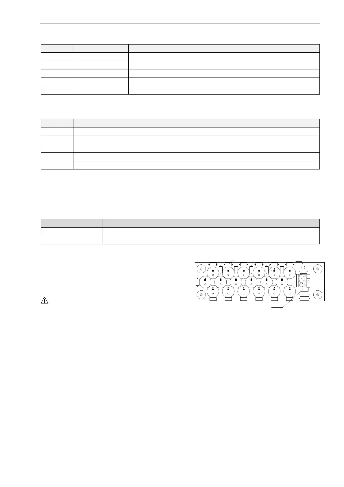
8.5 SUPERCAPACITOR BANK
The bank is a reservoir of electric energy stored in supercapacitors
(high capacity capacitors). The purpose is to supply each
gearmotor in blackout condition, so that the voltage regulator can
reach its minimum voltage position.
Supercapacitors are used when electrolytic capacitors are not
performant enough to carry out said operation (large rating and/or
large input variation range).
WARNING THE VOLTAGE AVAILABLE ON THE BANK IS NOT
DANGEROUS. HOWEVER, BECAUSE OF ITS FUNCTION, THE CARD
STORES ELECTRIC ENERGY AND MIGHT STAY CHARGED EVEN AFTER HAVING BEEN DISCONNECTED FOR A FEW MINUTES. DO
NOT SHORT-CIRCUIT THE CARD AND DO NOT POSITION CONDUCTIVE AND/OR METALLIC OBJECTS IN THE VICINITY. ANY
RESIDUAL VOLTAGE CAN BE EASILY DETECTED BY MEANS OF THE LED MOUNTED ON THE CARD: WHEN THE LED IS ON, THE
CAPACITORS ARE CHARGED AND VOLTAGE IS AVAILABLE.
Some resistors might be hot. The bank can be regarded as discharged after five minutes from disconnection.
A green LED shows that the bank is supplied and working correctly.
A varistor surge ARRESTOR intervenes in case of overvoltages.
protector
DL1
D1
LED
resistor supercapacitor
-
+