ORTEA SpA MAT200 aug21
15 / 24
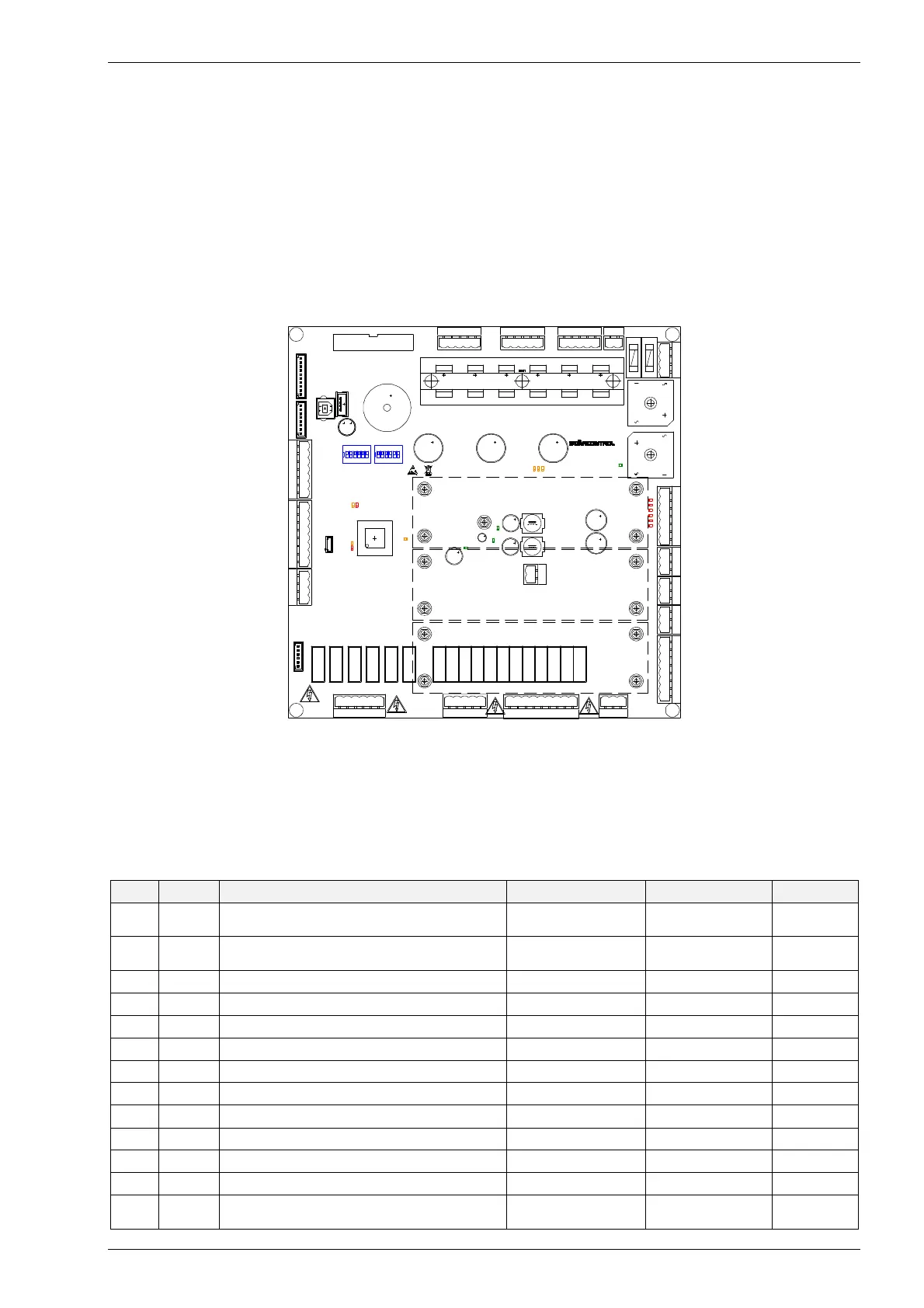
8 CONTROL CARD
The control card runs the voltage stabiliser by regulating each phase independently and also monitors the output currents
and generates an alarm in case of overcurrent. Under normal working conditions, the output voltage is maintained stable
with an accuracy equal to ±0.5% in relation to the rated voltage. The control is performed totally through a software that
digitalises all the parameters (full digital control).
The card is fitted with a DSP microprocessor (DIGITAL SIGNAL PROCESSOR) that works as a controlling and measuring CPU. By
means of this device, the card reads line voltage, settings, motor current and inputs and drives each motor directly by
imposing direction and speed. On the basis of the motor current, the card elaborates also the protections against overload
and short-circuit for the motor itself. Firmware and operational parameters can be updated by means of a USB drive. The
following components are connected to the control card:
signalling card connected via a flat wire to P2 terminal on the control card;
supercapacitor banks for adjusting to minimum voltage position in case of blackout (when fitted).
Note Due to the presence of miniaturised components and possibility of micro-fractures, the card must not be bent.
Note For software and parameters updating procedure and means, please contact the Service Dept..
8.1 PROTECTIONS
8.1.1 Motor stop or overload
The control estimates if the motor is overloaded or either the motor or the relevant kinematic mechanism is blocked. The
thermal energy (i.e. the current) released is measured and if the value exceeds a set threshold, an alarm is generated.
8.1.2 Short-circuit
The card is provided with a phase-to-phase short-circuit alarm for each motor. Filtering devices operate in order to avoid
unnecessary intervention. The resistance to a short-circuit depends on the nature of the phenomenon.
8.2 CONTROL CARD LEDS
REF. COLOUR PARAMETRE ON OFF BLINKING
D62 yellow CPU activity CPU blocked
absent SW
Status OK
D63 red Active alarm signal
alarms
No active alarm
status
D93 yellow CPU programming - Normal status -
D92 red CPU programming - Normal status -
D60 red Spare 1 input active inactive -
D65 red Spare 2 input active inactive -
D68 red Current alarm input active inactive -
D71 red Temperature alarm input active inactive -
D74 red Fan alarm input active inactive -
D147 red Spare 3 input (NOT USED) active inactive -
D143 yellow Phase U motor current limitation intervention Active limitation Inactive limitation -
D144 yellow Phase V motor current limitation intervention Active limitation Inactive limitation -
D145 yellow
Phase W motor current limitation
intervention
Active limitation Inactive limitation -
microprocessor
1
1
1
1 PHASE ADJMT P/B 8
P10
3
PHASE ROLLER
P18
D65
8
+12V
P34
1 T A INPUT 4
D92
P14
P6
F1
3
D79
1
7 ALARMS 1
1
PHASE OUTPUT
SIREN-MAX V/MINV-REM.AL.
1
D75
D147
LED PANEL + BUZZER OFF P/B
D62
P29
SCAP EXT RES
P30
6
P15
SW1
P3
P11
3
SWITCH_B
1
1 CAN BUS 10
+ SCAP1 -
F2
1
OUTPUT 1
NO COM NC
D82
P12
P27
1 U_MOTOR 5
P37
D74
P19
P33
P1
P36
VPOT
D42
1
3
SWITCH_A
1 W_MOTOR 5
1
+ MAX 2A -
8
+5V
P4
+ SCAP2 -
USB
D71
D93
6
P5
OUT 24V
PHASE INPUT
D145
D60
P20
P2
1 PHASE ADJMT TRIMMER 7
7 8 9 10 11 12
P35
+ SCAP3 -
3
D146
P32
D143
9
D68
D63
1
4 BOARD SUPPLY 1
5
D144
1
1 2 3 4 5 6
1 V_MOTOR 5
P31
P17
SW2
PC
BZ1