ORTEA SpA MAT200 aug21
18 / 24
9 ALARMS & SERVICE
DANGER ACCESS TO THE INTERNAL COMPONENTS MUST BE GRANTED ONLY TO QUALIFIED, TRAINED PERSONNEL IN
CHARGE OF IT. ANY OPERATION THAT MIGHT REQUIRE THE UNIT TO BE ENERGISED MUST BE CARRIED OUT IN COMPLIANCE
WITH THE HABITUAL RULES CONCERNING PERSONAL SAFETY AND THE USE OF ADEQUATE PROTECTIVE TOOLS.
In case of anomalies or failure of any component, check that all the instructions given in this manual have been followed.
Interventions must be requested out promptly as soon as the issue arises in order to avoid an aggravation of the problem
and the involvement of other components.
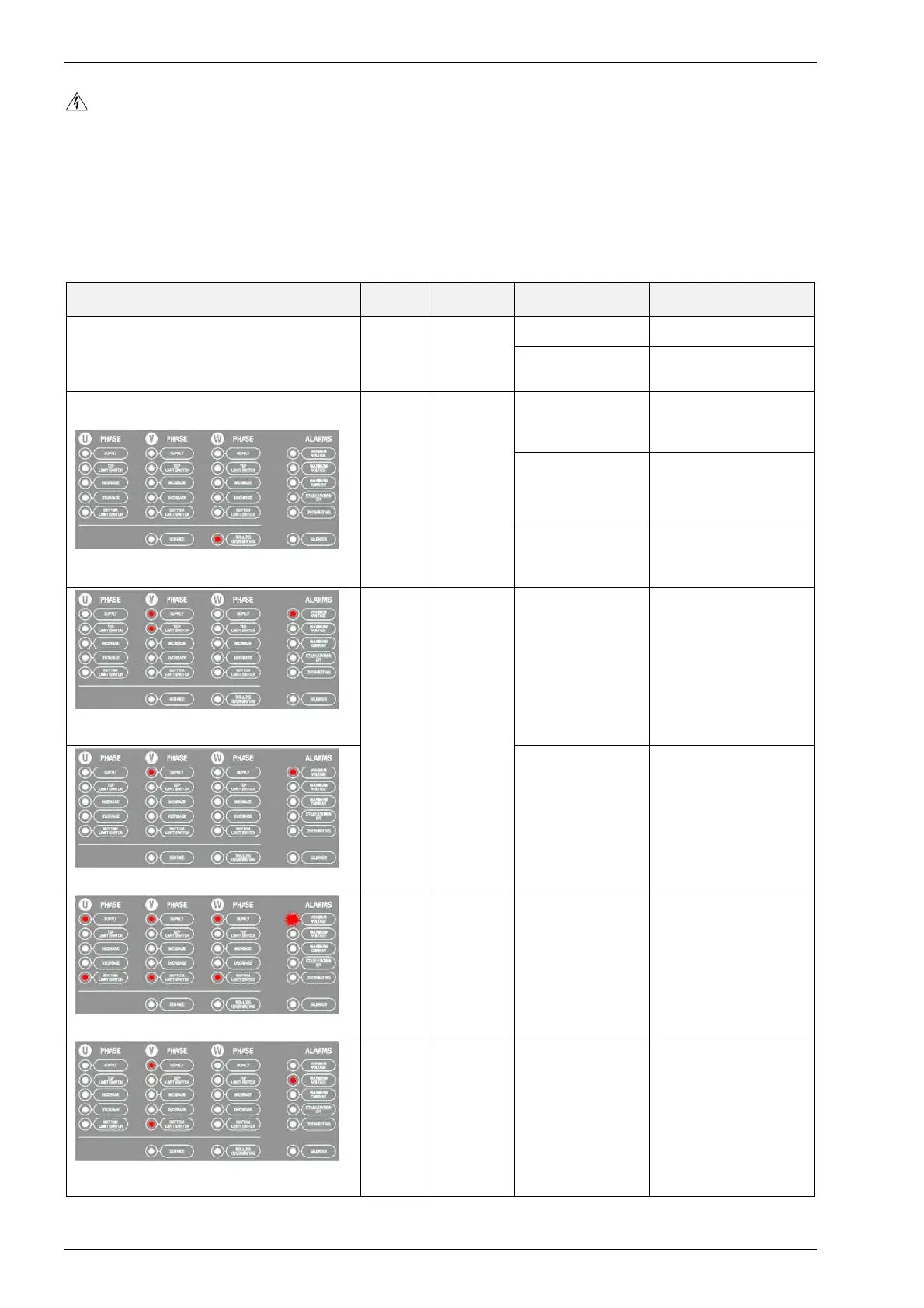
9.1 ALARM SIGNALS
Note With reference to the table below, the REM1 relay is connected to the P37 terminal block and the REM2
relay is connected to the P18 terminal block.
ALARM SIGNAL
ACTIVE
RELAY
ISSUE POSSIBLE CAUSE ACTIONS
Blank instrument display N.A.
NO READING
ON THE
INSTRUMENTS
Damaged or
defective instrument
Replace with spare
instrument
Fuse intervention
Check the supply.
Replace the blown fuse
with an equivalent one
REM1
REM2
ROLLER
OVERHEATING
Overload on the
regulator
Check column surface
(colour). Investigate and
eliminate the overload
source.
Failure of the thermal
probe on the central
roller of each roller
group
Switch the unit off and
check if the thermal probe
connection is interrupted.
Probes are connected in
series.
Presence of dirt or
dust on the regulator
surface (incorrect
roller contact)
Switch the unit off and
clean the regulator
following the maintenance
procedure.
SUPPLY & TOP LIMIT SWITCH LEDS (CONCERNED
PHASES)
MIN-MAX
REM1
MINIMUM
VOLTAGE
V
out
lower than V
target
beyond the set
tolerance (default:
6%)
Check incoming voltage.
Wait until the nominal
condition is re-established.
MIN VOLTAGE LED AS CONSEQUENCE
Locked gearmotor
Switch the unit off and try
to manually move the
carriage and therefore the
motor. If necessary,
replace with a spare one.
MIN VOLTAGE LED BLINKING
MIN-MAX
REM1
MISSING
PHASE(S)
Card signal defective
(P30) or mains
deficiency
The unit could be working
correctly. Check the
voltage parameters on the
instruments and/or by
measuring at the unit I/O
terminals.
Check that P30 terminal is
correctly connected.
If necessary replace the
card with a spare one.
SUPPLY & BOTTOM LIMIT SWITCH LED (CONCERNED
PHASES)
MIN-MAX
REM1
MAXIMUM
VOLTAGE
Same as for
Minimum voltage but
with V
max
LED
Check incoming voltage.
Wait until the nominal
condition is re-established.