ORTEA SpA MAT200 aug21
16 / 24
REF. COLOUR PARAMETRE ON OFF BLINKING
D42 green Card supply 28VDC present 28VDC absent -
D75 green +12VDC supply 12VDC present 12VDC absent -
D79 green +5VDC supply 5VDC present 5VDC absent -
D82 green +3,3VDC logic supply Present absent -
8.3 CONTROL CARD TERMINALS
REF. TYPE DESCRIPTION
P1 34-pole male flat Panel interface
P2 6-pole male Phase U motor
P3 6-pole male Phase V motor
P4 6-pole male Phase W motor
P5 4-pole male Card supply
P6 10-pole AMP MODU2 male CAN bus
P10 7-pole male Alarm inputs
P11 7-pole male Phase regulation potentiometres
P12 3-pole male supercapacitors
P14 8-pole male phase regulation push-buttons
P15 3-pole male supercapacitors
P17 3-pole male supercapacitors
P18 6-pole male Alarm outputs
P19 8-pole male Regulated voltage input – dangerous voltage
P20 4-pole male Three-phase CT currents input
P30 2-pole male Output LED card supply
P31 Type B USB PC connection slave USB
P32 Type A USB USB drive connection master USB
P33 2-pole male Connection to external 1ohm resistor for supercapacitor
P34 6-pole 1.255mm connector CPU programming
P35 5-pole male Unregulated voltage input – dangerous voltage
P36 9-pole male Regulator contacts voltage input – dangerous voltage
P37 3-pole male Alarm outputs (relay)
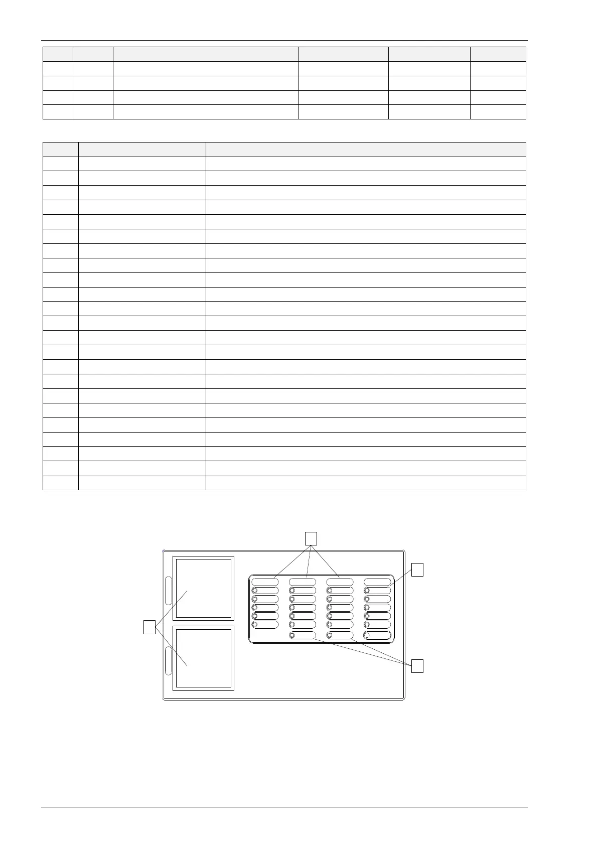
8.4 EXTERNAL CONTROL PANEL AND SIGNALLING CARD
The panel is the interface towards the user and provides with all the relevant readings and alarm signals. The card is
mounted behind the control panel and is connected to the control card via a flat wire.
U2
SUPPLY
TOP LIMIT
SWITCH
INCREASE
DECREASE
BOTTOM LIMIT
SWITCH
INCREASE
DECREASE
BOTTOM LIMIT
SWITCH
BOTTOM LIMIT
SWITCH
INCREASE
DECREASE
TOP LIMIT
SWITCH
SUPPLY
V2
SUPPLY
TOP LIMIT
SWITCH
W2
MAXIMUM
CURRENT
STABILIZATION
OFF
OVERHEATING
SILENCER
ALARMS
MINIMUM
VOLTAGE
MAXIMUM
VOLTAGE
I
N
P
U
T
O
U
T
P
U
T
A
C
B
SERVICE
ROLLER
OVERHEATING
D
8.4.1 A – instrumentation
Input and output readings.