5
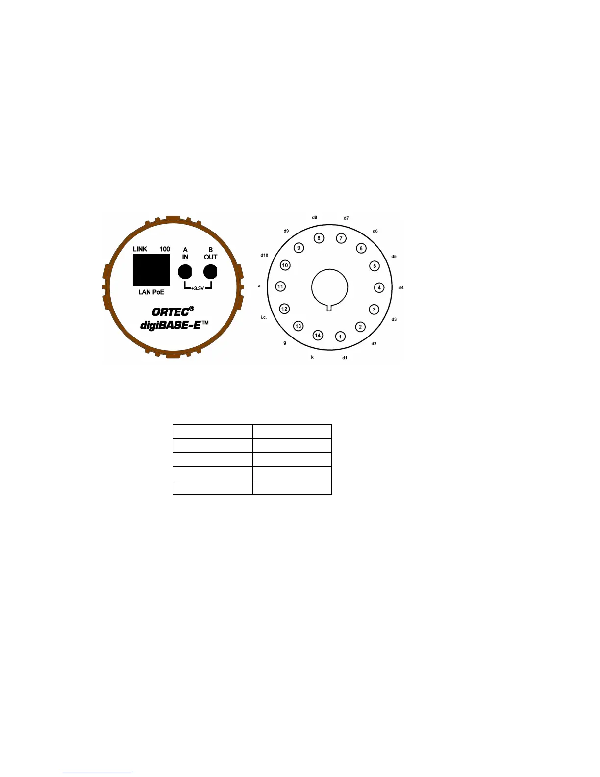
Figure 1. The digiBASE-E Connectors.
2. GETTING STARTED
2.1. The digiBASE-E
Figure 1 shows the digiBASE-E connectors on both the top and bottom panels, including the pin
assignments for the socket base, which accepts JEDEC B14-38 PMT pin bases (Table 1). The
digiBASE-E operates on Power over Ethernet (PoE). The CAT5E Ethernet cable runs to a
single-port PoE injector that requires an ac power source (see the specifications in Chapter 4).
2.2. Data Acquisition (Gate) Modes
In multi-detector measurement systems, there is often a need to synchronize data acquisition (for
example, in a mobile gamma-ray search system the data from all detectors must be correlated to
correctly map the activity distribution over an area). The digiBASE-E provides flexible gating
features; events from multiple spectrometers may be correlated to within <100 milliseconds.
This is achieved by the use of a gate input and a gate output.
d1–d10 dynodes 1–10
a anode
i.c. internal connection
ggrid
k cathode
Table 1. JEDEC B14-38 PMT Pin Base Pinouts.