2. GETTING STARTED
7
d) Close and reselect the MAESTRO spectrum window for this digiBASE-E. The
histogram in the alternative data memory will be displayed in the MAESTRO
spectrum window.
e) To return to the regular histogram memory, enter
SET_VIEW 0, click on Send, then
close and reselect the MAESTRO detector window for this digiBASE-E to redisplay
the regular spectrum histogram.
! Sync — This applies only to list mode and a daisy-chain configuration (maximum 12 units
per daisy chain). Input A is the time synchronization pulse. A transition from low to high at
Input A causes a sync timestamp to appear in the list mode data stream. Requires customer-
written software.
! SyncMaster — This applies only to list mode and a daisy-chain configuration. In a
daisy-chained setup (maximum 12 units per daisy chain), only one digiBASE-E can act as
SyncMaster. The SyncMaster is responsible for generating a pulse at 100 ms intervals, and
the pulse is replicated to the other daisy-chained digiBASE-Es. Requires customer-written
software. Your software must distinguish the IP address of the master unit from the slaves.
2.3. Software and Hardware Installation
Installation takes just a few straightforward steps. See the quick-reference diagram in Fig. 2.
1. Install the accompanying C
ONNECTIONS Driver Update Kit (p/n 797230) first, being sure to
mark the DigiBASE-E checkbox on the Instrument Families screen.
2. If using ScintiVision-32, install it before installing MAESTRO.
3. Install the accompanying MAESTRO MCA Emulation Software (A65-BW).
4. Set the digiBASE-E’s coarse gain jumper as desired (the factory default is 1×), then mount
the detector on the digiBASE-E.
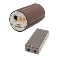
5. Connect the single-port PoE injector to an ac power supply
6. Connect the PoE injector to a network or a host PC.
7. Connect the digiBASE-E to the PoE injector.
8. Run the accompanying digiBASE-E Ethernet Device Controller program to locate all
digiBASE-Es on the network, and attach to the desired unit(s). Be sure to read
Section 2.3.4.1 on IP addressing.
9. Run the MCB Configuration program to establish communication between the digiBASE-Es
(and any other ORTEC MCBs) and your ORTEC software application(s).
NOTE Note that the SET_VIEW command affects only the PC that issued the
command. A user who accesses the same digiBASE from a different PC will
initially see the regular (SET_VIEW 0) spectrum view.