EN
52
EN
REV. 01 - Cod.: 1500288Operation and maintenance manual / Ed. 11 - 2008
CUISSON SV-31 • SV-41
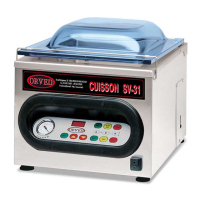
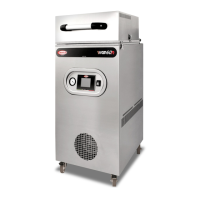
7.4.6 REPLACING FUSES
MAINTENANCE
7.4.5 WIRING DIAGRAMS
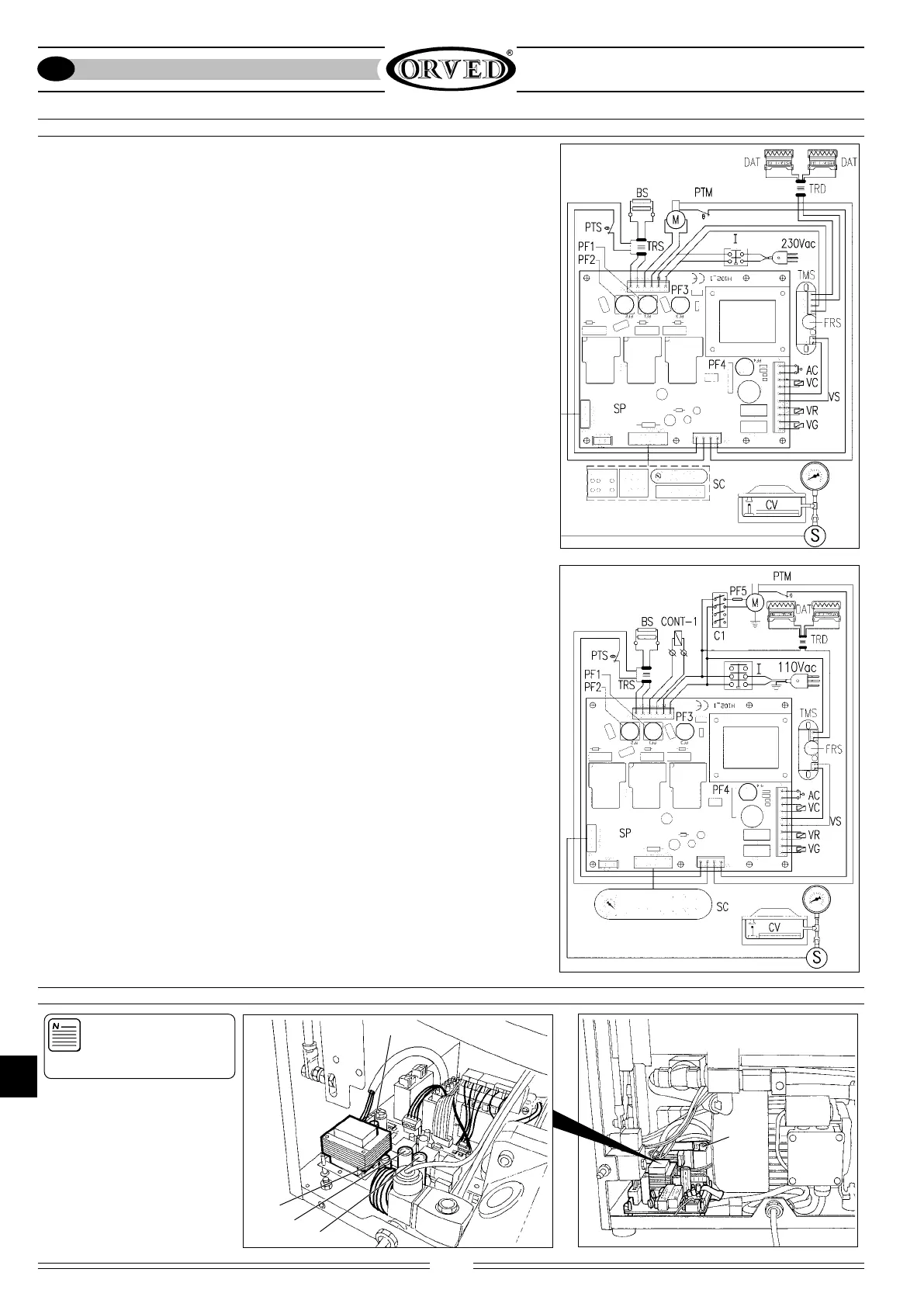
7.4.6.1 WIRING DIAGRAMS 230V
TRS Sealing Transformer
BS Sealing bar
M Vacuum pump
I Main switch
PF1 Fuse holder with 2/6.3/8/10A vacuum pump fuse
PF2 Fuse holder with 2.5-8/2.5-10A sealing fuse
PF3 Fuse holder with 1A power board fuse
PF4 Fuse holder with 4A power board fuse
AC Machine work cycle start-up
VC Sealbag valve
VS Dater power supply impulse
VR Vacuum chamber return air valve
VG Optional gas function valve
SC Digital control board
SP Power board H 102_1
CV Vacuum chamber
S Vacuum sensor
PTM Pump motor thermal protector
PTS Sealing Transformer thermal protector
FRS Dater safety timer fuse
TRD Dater power supply transformer 0-230-380/0-4.4V
DAT Dater
TMS Dater power supply safety timer
7.4.6.2 WIRING DIAGRAMS 110V
TRS Sealing Transformer
BS Sealing bar
M Vacuum pump
I Tripolar Main switch
PF1 Fuse holder with 2/6.3/8/10A vacuum pump fuse
PF2 Fuse holder with 2.5-8/2.5-10A sealing fuse
PF3 Fuse holder with 1A power board fuse
PF4 Fuse holder with 4A power board fuse
AC Machine work cycle start-up
VC Sealbag valve
VS Dater power supply impulse
VR Vacuum chamber return air valve
VG Optional gas function valve
SC Digital control board
SP Power board H 102_1
CV Vacuum chamber
S Vacuum sensor
PTM Pump motor thermal protector
PTS Sealing Transformer thermal protector
FRS Dater safety timer fuse
TRD Dater power supply transformer 0-110/0-4,4V
DAT Dater
TMS Dater power supply safety timer
C1 Pump electromagnetic switch coil 110V (includes CONT-1)
WARNING: This opera-
tion must be performed
only by qualified per-
sonnel.
1) Disconnect the plug from the
mains socket.
2) Remove the rear panel and
remove the fusebox capsule by
rotating it anticlockwise through
half a turn and replace the burnt
fuse with a new fuse having
identical features (See
Technical Data Table page 34).
PFT
•
•
•
•
PF3
PF1
PF2
PF4