Battery charger for the PUMA T2 hand-held radio
Technical Manual
Functional Description
Page 32 OTE Proprietary Information
P/N: 779-0357/02
Revision 04
Note
The BCU6-750, with three couples of charging slots, is equipped with three identical cards.
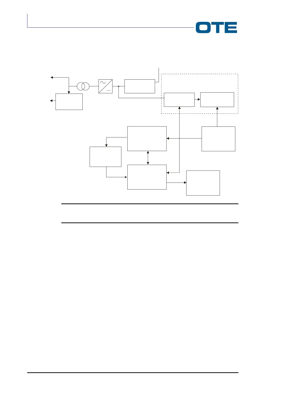
Fig. 3.8: BCU2-1500, BCU2-1500/B and BCU6-750 block diagram
A constant voltage (13 V) is the stabilizer input and in ouput we have a voltage
suitable with the supply of the 6 V circuits. The comparator’s function is to stop the
Li-Ion battery charging when it detects that the current value is lower than a
threshold value.
The block called Voltage Control has to regulate the battery voltage value in order
to stop the constant current battery charging phase. the DC/DC conververter
modulates (PWM) the 13 V input constant voltage. The microprocessor controls
the voltage step in order to have a correct mean value for the battery charghing.
A multiplexer manages the working of the oscillator previously described.
The battery presence/status detection block detects the presence of the battery in
one of the two slots.
The integrator manages the constant current charging phase by varying the
voltage in accordance to the impedence’s variation.
6 V STABILIZED
VOLTAGE
GENERATOR
DC/DC
CONVERTER
13 Vdc
RECTIFIER
TRANSFORMER
VOLTAGE
SELECTION
SWITCH
230 V/115 V
230 V
(BCU2-1500)
230 V/115 V
(BCU2-1500/B
and BCU6-750)
VOLTAGE
CONTROL
COMPARATION
CONSTANT CURRENT
CHARGE MANAGING
BATTERY
PRESENCE/STATUS
DETECTION
MICROPROCESSOR
INTEGRATOR
LEDS
CIRCUIT