See also General warning notes ► 36.
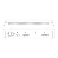
For a detailed description of the connection panel, see the AURICAL AudReference Manual.
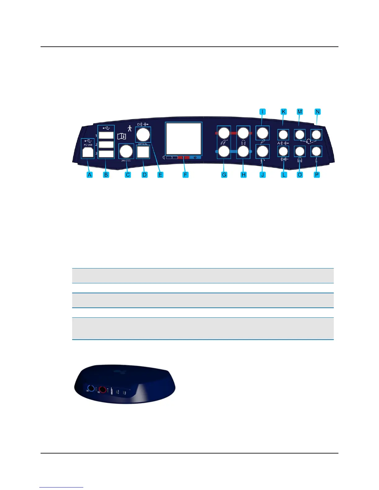
Connection panel - AURICAL Aud
A. PC/USB connection
B. Powered USB connections for accessories
C. External power supply
D. Sound field speaker output (optical digital line-out)
E. Sound field speaker output (coaxial digital line-out)
F. Sound field speakers (power output)
G. Insert earphones
H. Headphones - air conduction
I. Patient Responder
J. Bone oscillator
K. Speaker, Analog (line output)
L. Line-in
M. Operator monitor headset - headphones
N. Operator monitor headset - boom microphone
O. Counseling and Simulations headphones
P. Talk-back microphone
Note • Blue corresponds to Left and red corresponds to Right.
Warning• Use only the power supply provided by Otometrics.
Caution • When you connect other electrical equipment to AURICAL Aud, remember that equipment that does not
comply with the same safety standards as AURICAL Aud can lead to a general reduction in the system's safety level.
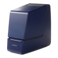
Connection panel - HI-PRO2
The HI-PRO2 connection panel contains the sockets for hearing
instrument connection cables, and light indicators relating to PC
communication and powering.
Otometrics - AURICAL Aud
7
5 Connecting accessories to AURICALAud