① Inspect for possible entrapment of air.
② If trouble is attributable to the valve position
indicator, inspect in the same manner as in
“Valve position indicator is dead.”
① Inspect associated equipment and field wiring
cables for condition.
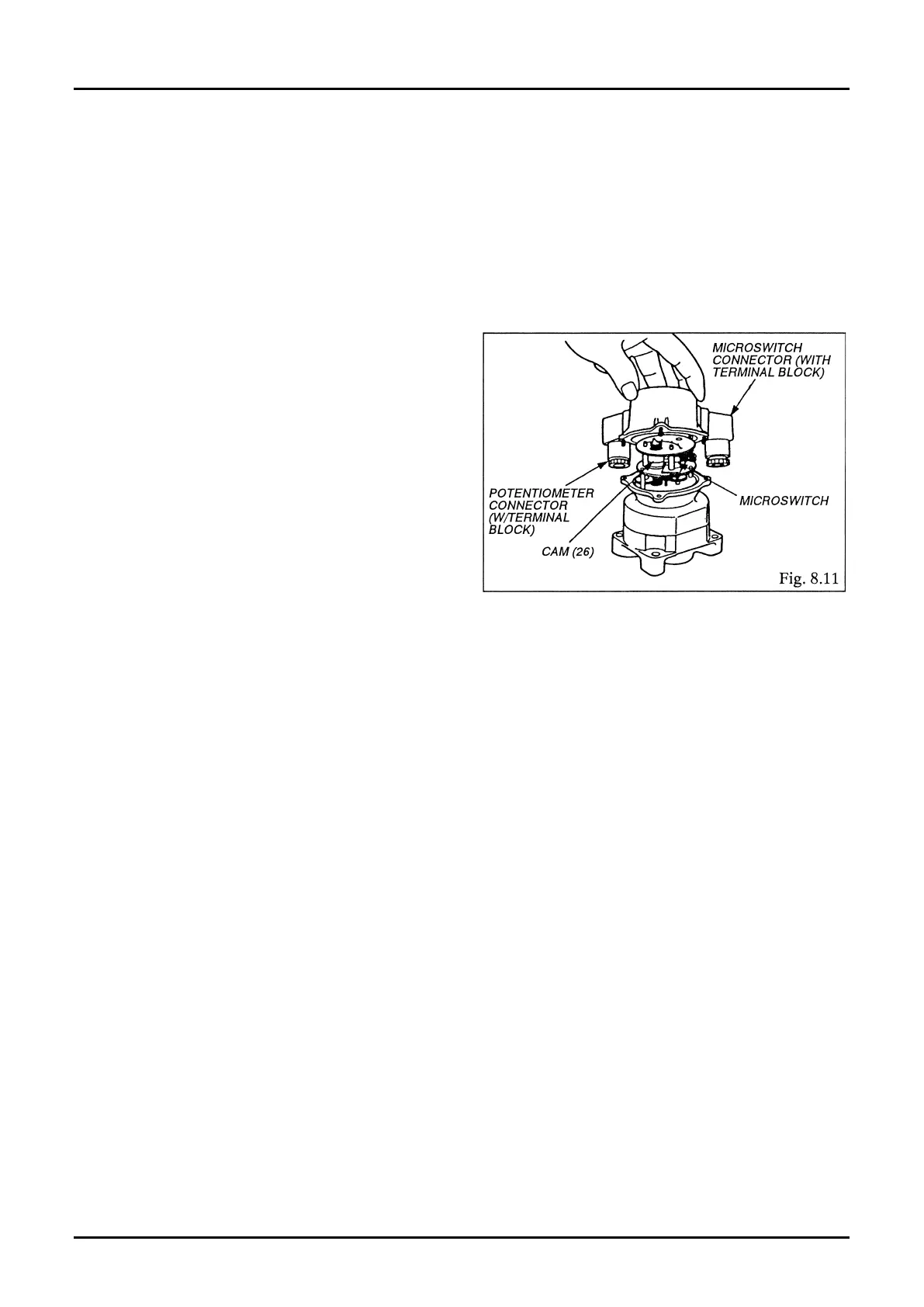
② Taking o M3 screws (17), remove the indicator
cover (11) (Fig. 8.11). Disconnect one end of wire
leads from its terminal and make a continuity
(on and o) check relative to valve opening and
closure with multimeter (in the ohm range). If
faulty condition persists with no signal output,
inspect the microswitches.
③ Possible causes for the absence of signal output
are:
(A) An open in the internal wiring.
(B) Microswitch positions out of adjustment.
(C) Microswitches are defective. If this is the
case, replace with new ones.
[See paragraph (6) in Section 9.4 Assembly
Procedure on page 19 for adjustment.]
① Inspect related equipment and eld wiring cables for condition.
② Possible causes for trouble are:
(A) An open or poor connections in the internal wiring.
(B) An open in the resistor. If this is the case, replace with a new one.
[See paragraph (5) in Section 9.4 Assembly Procedure on page 19 for adjustment.]
① It is recommended that the valve position indicator be disassembled and inspected on a regular basis
(once every three years or so).
② Seals, including O-rings, should be replaced with new ones each time a periodic disassembly and
inspection is performed.