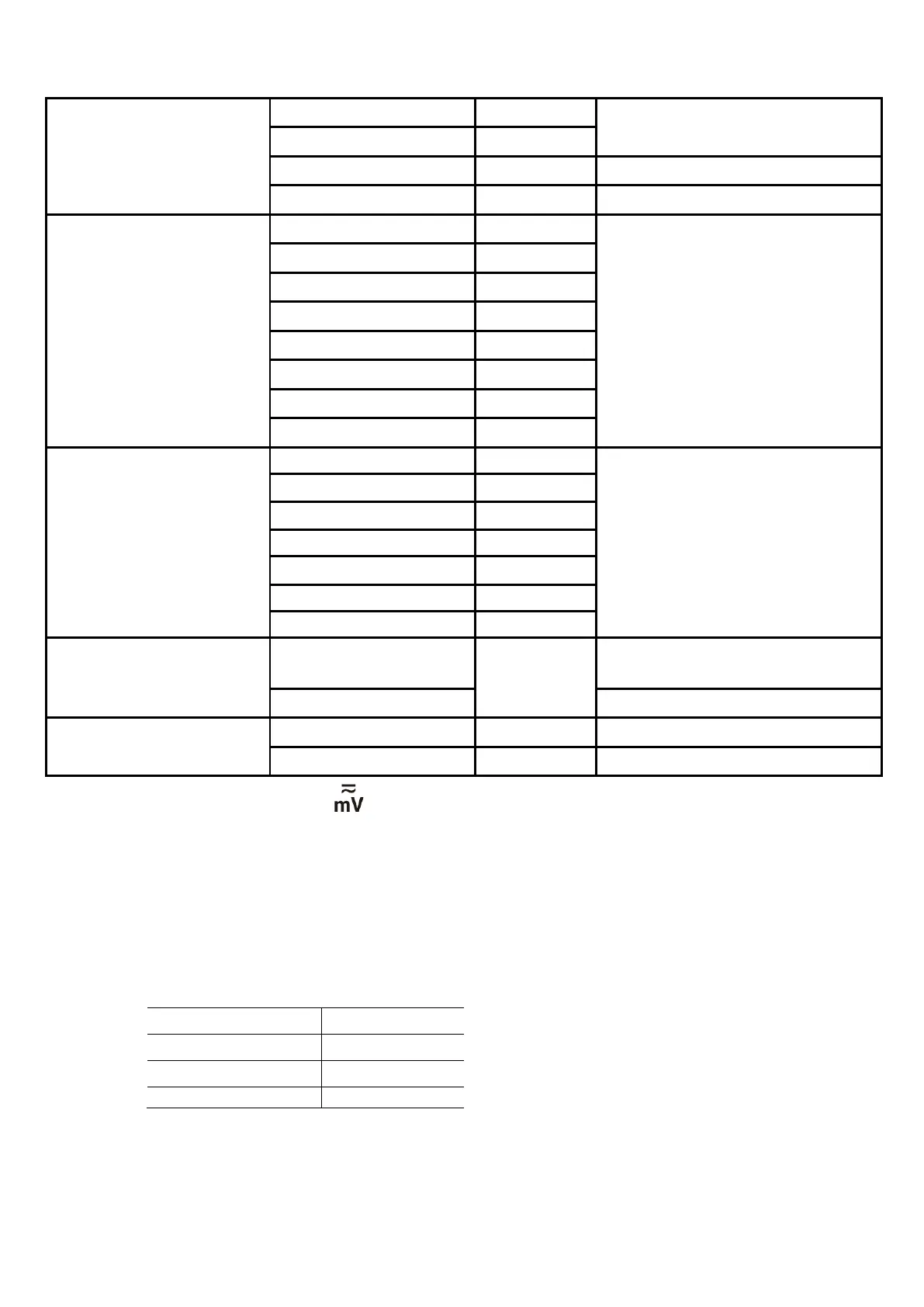
7.Technical Specifications
200.00kΩ
10Ω
2.0000MΩ
20.000MΩ
±(0.5%+1dig)
200.00MΩ 10kΩ ±(5.0%+10dig)
Capacitance (F)
2.0000nF 0.01pF
±(3.0%+10dig)
20.000nF
200.00nF
2.0000μF 100pF
20.000μF 1nF
200.00μF
2.0000mF
20.000mF
1μF
Frequency
[4]
(Hz)
±(0.1%+4dig)
200.00kHz
Duty Cycle
[5]
(%)
0.1% - 99.9% (Typical:
Vrms=1 V, f=1 kHz)
0.10%
±(1.2%+3dig)
0.1% - 99.9%(≥1 kHz) ±(2.5%+3dig)
Temperature (°C/°F)
-50 ℃ to 400 ℃ 1 ℃ ±(1.0%+3℃)
-58 ℉ to 752 ℉ 1 ℉ ±(1.2%+6℉)
[1] The rotary switch position is only for specific models.
[2] When measuring current, for 10 A to 15 A, the measuring duration should not be over 2
minutes within 10 minutes, and in this 10 minutes, no other current should flow through
except within the measuring duration; for 15 A to 20 A, the measuring duration should not be
over 10 seconds within 15 minutes, and in this 15 minutes, no other current should flow
through except within the measuring duration.
[3] When measuring capacitance, for the 20.00mF range, the measuring duration should be over
30 seconds.
[4] When measuring frequency, the typical waveform is Square or Sine. The signal meets the
following conditions.
[5] When measuring duty cycle, the typical waveform is Square.
Note: when measuring resistance and capacitance, the influence of the resistance reactance of
the pen itself on the measured value should be considered.
44
 Loading...