Do you have a question about the Owon HDS series and is the answer not in the manual?
Explanation of warning symbols and terms used in the manual.
Precautions for avoiding personal injury and product damage.
Description of power adapter, test leads, and multimeter jacks.
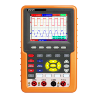
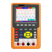
Identification and function of front panel ports and buttons.
Steps for connecting power and starting the oscilloscope.
Instructions on how to access and select functions using the menus.
How to manually adjust vertical scale, time base, and trigger position.
Term interpretation for scale, zero position, time base, and trigger level.
Procedure to reset the oscilloscope to factory default settings.
Details on BNC and banana jack inputs for scope and multimeter.
Using Auto Set to automatically optimize display for unknown signals.
Performing and displaying automatic measurements like frequency and peak-peak.
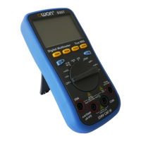
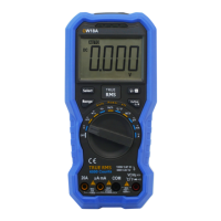
Connecting test leads to the meter for various measurements.
Steps to switch to multimeter mode and prepare for measurements.
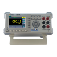
Procedure for measuring resistance using the multimeter.
Procedure for testing diodes with the multimeter.
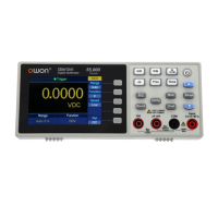
Procedure for measuring DC voltage with the multimeter.
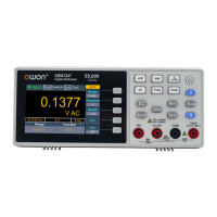
Procedure for measuring AC voltage with the multimeter.
Procedure for measuring DC current below and above 400mA.
Procedure for measuring AC current below and above 400mA.
Configuring trigger mode, level, and position for stable waveforms.
Adjusting trigger level position.
Using Edge and Video triggering modes for signal acquisition.
Triggering based on signal edge crossing a specific level.
Edge trigger menu settings: slope, source, mode, coupling.
Performing 20 types of automatic measurements like frequency, average, Vmax.
Measuring frequency of CH1 and peak-peak of CH2 as an example.
Automatically setting trigger, voltage, and time scales for signals.
Notes on Autoscale function behavior and interaction with other modes.
Solutions for power issues, stopped operation, ERR messages, and unstable waveforms.
| Channels | 2 |
|---|---|
| Bandwidth | Up to 100 MHz |
| Multimeter Functions | Voltage, Current, Resistance, Capacitance |
| Resistance Measurement Range | 400Ω ~ 40MΩ |
| Power Supply | Lithium Battery |
| Connectivity | USB |
| Battery Life | About 6 hours |
| Weight | Approx. 500 g |
| Duty Cycle Range | 0.1% to 99.9% |
| Data Storage | Internal memory |
| Voltage Measurement Range | 400mV ~ 1000V |
| Current Measurement Range | 0.1 μA to 10 A |