Operation
The top label and LEDs convey some basic information that aids configuration and
troubleshooting. Once power is applied, the RT requires no further input from the user to
start logging and outputting data.
This section covers some basic information required for operation of the RT.
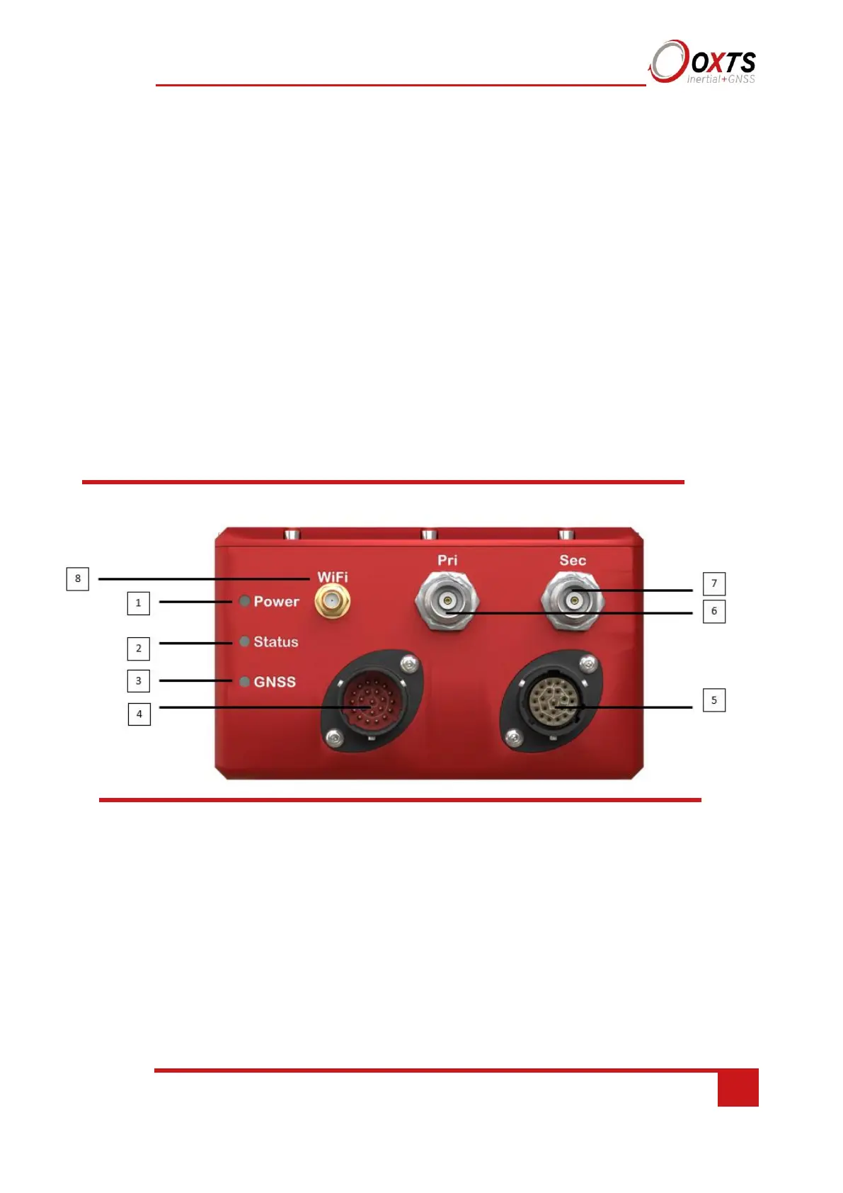
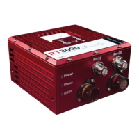
Front panel layout
Figure 3 shows the layout of the RT500 and RT3000 front panel. Table 7 lists the parts
of the front panel labelled in Figure 3. For single antenna models, the secondary
antenna connector is not connected internally.
Figure 3. RT500/RT3000 front panel layout