Do you have a question about the OXTS RT3000 and is the answer not in the manual?
Information for contacting Oxford Technical Solutions for support and inquiries.
Oxford Technical Solutions Limited warrants products against defects in materials and workmanship for one year.
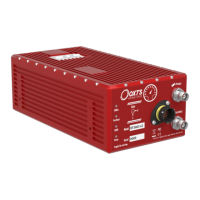
Overview of the RT system divisions, including RT500s and RT3000s models.
Details on using a single antenna system for heading and slip features.
Information on dual antenna systems for improved heading accuracy.
Simplified system setup and operation with minimal configuration required.
RT uses GNSS to correct its measurements, preventing drift.
RT500 and RT3000 products have identical output capabilities.
Proprietary gx/ix™ processing engine for improved performance in poor GNSS.
List of supplementary manuals providing further information on software and communication.
Proper mounting and alignment of the RT for accurate measurements.
Essential placement and orientation guidelines for GNSS antennas for optimal performance.
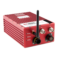
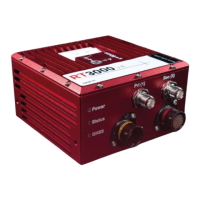
Explanation of the RT500 and RT3000 front panel components and indicators.
Definition of the IMU reference frame used by the RT for measurements.
Susceptibility of dual antenna systems to multipath errors and their impact.
Description of signals on the digital I/O connector J5.
Description of the 1PPS pulse output generated by the GNSS receiver.
Configuring wheel speed input to reduce drift when GNSS is unavailable.
Key parameters the RT needs for optimal performance, including orientation and antenna positions.
Guide to using the NAVconfig software for device configuration and settings.
Initial steps in NAVconfig: new configuration, modifying, or improving settings.
Options for loading initial configuration settings from a device, file, or folder.
Settings for RT and antenna positions and vehicle profile.
Defining the vehicle's coordinate frame relative to the RT's coordinate frame.
Inputting primary GNSS antenna position for accurate measurements.
Configuring the secondary antenna for dual antenna systems to compute heading.
Configuring GNSS differential correction message types for improved accuracy.
Using Networked DGPS (WLAN) for differential corrections via Wi-Fi.
Using SBAS for differential corrections to improve RT position accuracy.
Configuring TerraStar corrections for high-accuracy positioning.
Options for configuring the RT's interfaces, including Ethernet and Wi-Fi.
Configuring Ethernet data output rate, packet type, and triggers.
Configuring the RT's Wi-Fi as an Access Point or connecting to an existing WLAN.
Configuring RT to send and receive data via CAN bus.
Defining incoming CAN signals for real-time viewing or logging.
Configuring serial port for different message types and baud rates.
Settings related to the environment and device initialisation conditions.
Settings related to device initialisation conditions and procedures.
Selecting predefined values for vehicle start conditions.
Selecting predefined values for GNSS environment conditions.
Selecting predefined values for vibration levels.
Option to lock heading when stationary to prevent drift.
Computing roll, pitch, and heading compared to a flat inclined surface.
Outputting displacement from an origin in a local coordinate grid.
Advanced settings for experienced users, including filters and calibration.
Simulating RT output to another location in the vehicle.
Filtering linear and angular acceleration before output.
Configuring wheel speed input to reduce drift when GNSS is unavailable.
Controlling how fast corrections are applied to outputs.
Advanced options for managing GNSS information and algorithms.
Changing coordinate frame settings for outputting positional information.
Editing specific and more accurate values for measurements.
Entering device-specific commands for features or actions.
Sending configuration changes to the RT via Ethernet or Wi-Fi.
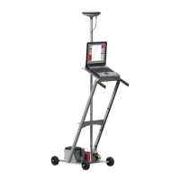
Details on using the RT-Base S, a self-contained GNSS, radio modem, and battery.
How outputs are generated during and after the initialisation process.
Applying improved settings to the RT using NAVconfig after the warm-up process.
Procedure to check if accelerometers are working correctly.
Procedure to check if gyros (angular rate sensors) are working correctly.
Checks to ensure internal circuits and navigation computer are functioning correctly.
Schematic view of the RT system's internal components.
Lists RT outputs on the CAN bus and identifiers for each message.
| Brand | OXTS |
|---|---|
| Model | RT3000 |
| Category | Measuring Instruments |
| Language | English |