Section 5
LABELING UNIT
- 22 -
English
F412050100.fmIDM
version
Module 40/60/90/120
On machines with a single control card (PL006):
you can set values from 0 to 3 (4 types of ramp). The
equivalence between the ramps of machines fitted with
the PL006 card and the ramps in the model with two
cards is illustrated in the table below:
Ramp 0 is the slowest and ramp 3 is the fastest. On the
faster machines, it is advisable to use ramp 0. On
machines up to 40-60 m/min, you can use ramp n. 2.
Ramp n. 3 is only used for narrow labels (less than 20
mm approx.).
P08 - Start Ramp
Setting a value other than zero increases the initial
speed of the ramp. P08 is normally set on zero.
P09 – Print time
This enables you to specify the duration of the pulse
destined for the marker. Each unit equates to
approximately 4 msec.
Initialize EPROM
When the machine is turned on, press “A + UP”
repeatedly while the “SW Ver.” message is showing.
When the word “Initialize?” appears, immediately
press Enter. Then the message “Initializing…” will
appear for a few instants.
Generally speaking, initialization is only needed in the
event of the program resident in the card being
updated; in this case, you will need to contact the
manufacturer for further details.
DESCRIPTION OF THE CONTROLS (VERSION 40 E)
The “MODULE 40 E” labeling unit for
self-adhesive labels is complete with a
power switchboard and a push button
control panel.
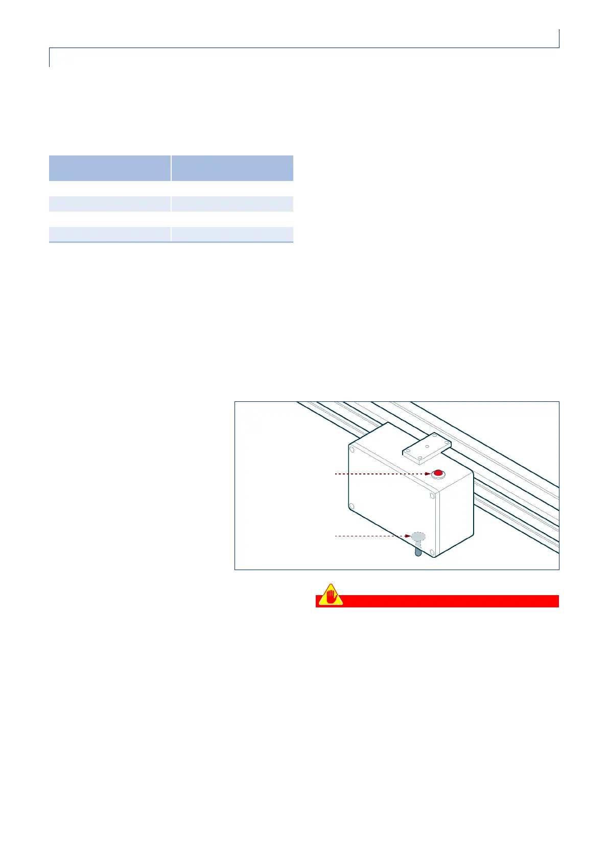
Switchboard
The switchboard, which is normally
installed on the support tubing
supporting the unit, contains the
general circuit breaker for the labeling
unit’s electric circuit and a red light that
comes on to indicate that the electric
circuit is powered. The red light is
situated on the top of the switchboard,
while the circuit-breaker is on the
underside. In certain special versions, the switchboard
may be installed in a less accessible position, in which
case the main circuit-breaker is situated on the push-
button control panel whenever possible.
1) Power-on red light
The light comes on when the switchboard is
connected to the power supply.
2) Main circuit-breaker
– Circuit-breaker in the "O" (OFF) position: the
labeling unit’s electric system is disconnected from
the mains power supply; the red power-on light is
off.
– Circuit breaker in the "I" (ON) position: the labeling
unit’s electric system is connected to the mains
power supply; the red power-on light is on.
Caution - Precaution
The labeling unit is essentially intended for use as
part of a labeling machine, not on its own.
The installer or user of the unit is consequently
required to install an isolator in compliance with
the EN standard 60204-1 upstream from the
connection powering the unit and provide an
emergency stop circuit in compliance with said
standard.
In fact, the main circuit-breaker normally installed
on the unit’s switchboard cannot be considered
as an isolator circuit-breaker or emergency stop
device in compliance with the EN standard 60204-1.
Ramp with single card
(PL006)
Ramp with two cards
(PL001+PL002)
0 3
1 5
2 6
3 7
IDM-41200603900.tif
1
2