68
Black: 18 gauge wire, printed [TURN SIGNAL SECTION] #969 HORN BUTTON
GROUND SOURCE, this wire is a ground source to the horn button. This wire will
provide a clean chassis ground source to the steering column. If you are using a GM or
Mopar steering column, this wire will not be needed.
Black/White: 16 gauge wire, printed [TURN SIGNAL SWITCH] #918 BRAKE LIGHT
SIGNAL, this wire will feed the brake light power into the turn signal switch for vehicles
with integrated turn/brake signals. This wire will have power anytime the brake pedal is
pressed. Those with separate turn and brake lights will not need this white #918 wire.
Route the Turn signal wires to the turn signal switch. If your hazard
switch is not on the column, black/brown wire #951 will route to the
hazard switch.
Using one of the following turn switch diagrams, connect each wire of
the Turn Signal Switch section to its correct connection.
GM Columns / Aftermarket GM style columns
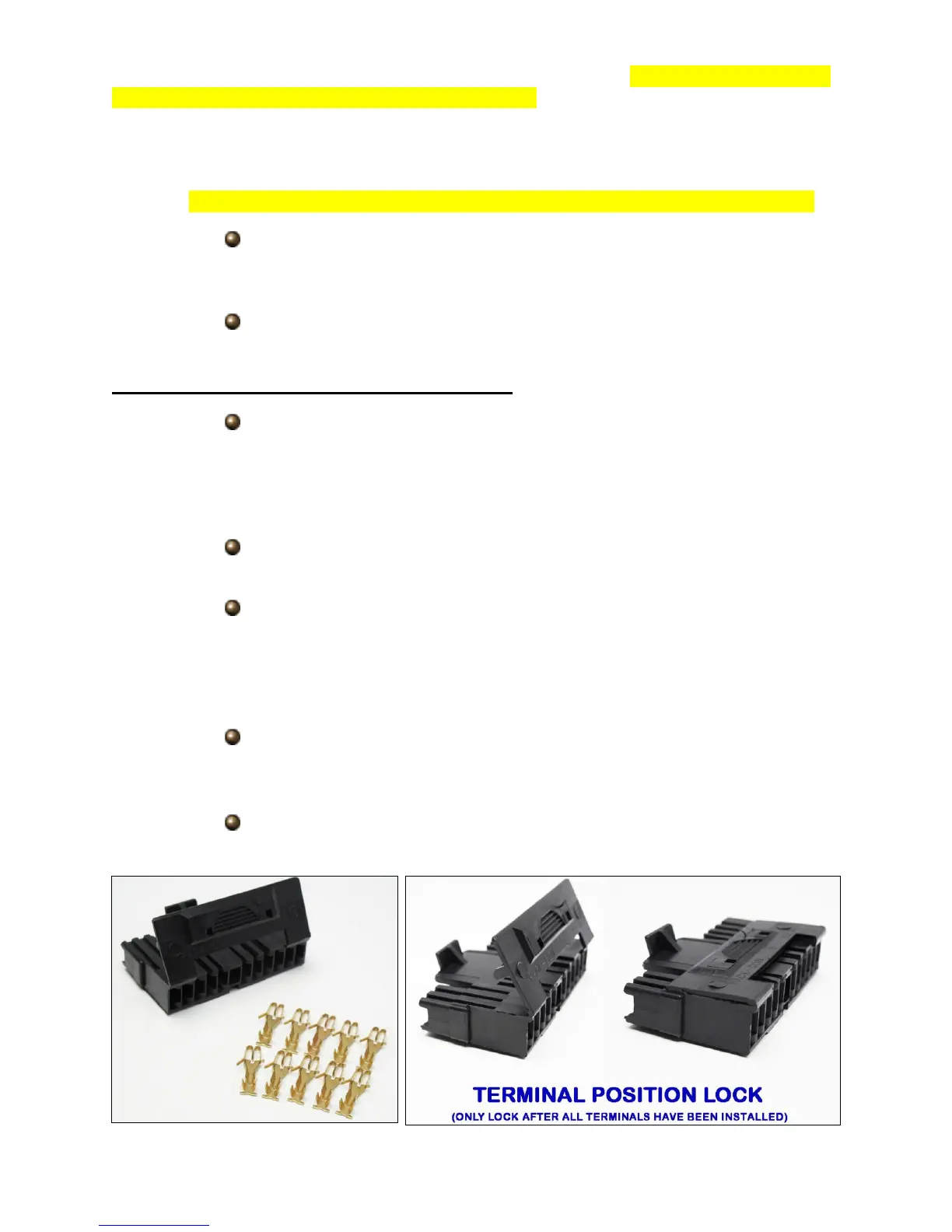
Locate the black connectors found in the bag kit that fits your column.
Most columns will use the 4 ¼” plug, seen below, found on most
aftermarket columns as well as mid 1970+ GM columns which are a
popular retro fit item because of their key on the column and tilt
function.
Locate the terminals supplied in the parts kit, seen below, and
terminate each wire of the Turn Signal Switch Section.
Using the diagram on the next page, pin each wire into its correct
location on the connector. Remember, black/white #918 will only be
connected if you have integrated lights. Also, black #969 will not be
needed; it may be connected to a clean chassis ground source or
removed from the harness.
If using the 4 ¼” connector, once all wires have been installed, fold the
locking tab down onto the connector. It will click/snap, locking the
terminal in their place.
Connect the now installed connector onto the connector on the
steering column.