75
Once installed, route this wire to the rest of the Turn Signal section Wires.
Remove the 2 prong flasher from the base you modified. Replace it with a
3 prong 12v flasher, not included. Slight modification/dimpling to the 3
prong flasher housing may be necessary to clear the mounting screw of
the flasher base on the fuse block.
Follow the manufacturers’ instructions on proper connections of the wires
from the switch.. #951 will connect to the wire the manufacturer states
goes to connect to “P on a 3 prong flasher”, the black/red wire that was
just added will connect to the wire labeled “L on a 3 prong flasher”.
Refer to the Turn Signal Schematic on page 77 to help match the wires of
your turn signal to the wires found on this chassis harness.
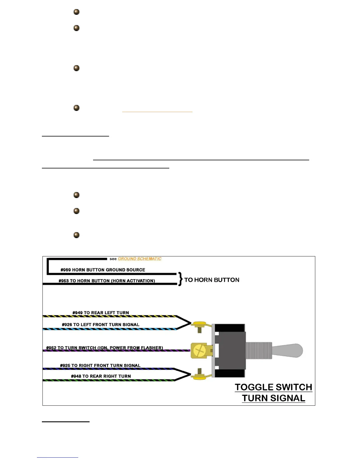
SPDT Toggle switch
If you do not have a turn switch, a simple On-Off-On SPDT switch can be used
for this function. Please be aware that the diagram and instructions provided below are
for separate turn/brake light vehicles only. Those with integrated lights are encouraged
to purchase Painless part #30120 or a clamp on turn signal switch as seen on the
previous few pages.
Connect the #952 wire to the input of the switch.
Connect the front and rear left turn signal wires, #926 & #949, to one
position on the switch.
Connect the front and rear right turn signal wires, #925 & #948, to the
remaining position on the switch.
Hazard Switch