74
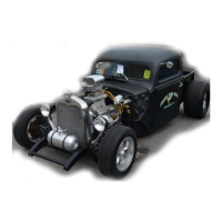
External/Clamp On Column Mounted Switch
There are many versions of this typical “hot
rod/street rod” style switch. In most cases this type of
switch will have wires coming from it in which the
chassis harness will connect. Do not try to match the
color of the wires on your switch to the striped colors
found on the Painless harness Due to so many
variations and manufacturers of this type of switch, a
specific pin out/ schematic cannot be given.
A 3 pin flasher is generally suggested with these
switches. This will allow the on board indicator lights of
the switch to function properly. The Painless harness you are installing comes equipped
with two 2 prong flashers which obviously will not work. However the fuse block can
easily be modified to accept a 3 prong flasher to allow the turn signal and turn indicators
on the switch to function properly.
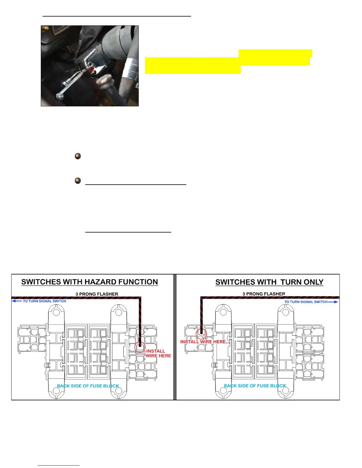
Locate the rolled piece of black/red wire provided with this kit. This wire
will have print reading “3 PRONG FLASHER”.
Switches with HAZARD function: Looking at the back of the fuse block,
locate the base for the hazard relay, this will be the top right base with two
black/brown wires. Plug the terminal pre-installed on the black/red wire
into the location circled in the diagram below. This will allow the turn
signals and hazards to work at all times.
Switches with TURN ONLY: Looking at the back of the fuse block, locate
the base for the turn signal relay, this will be the single base to the left with
two black/purple wires. Plug the terminal pre-installed on the black/red
wire into the location circled in the diagram below. This will allow the turn
signals to only work when the ignition is in the ON/RUN position.