1.4 System Hardware Configurations
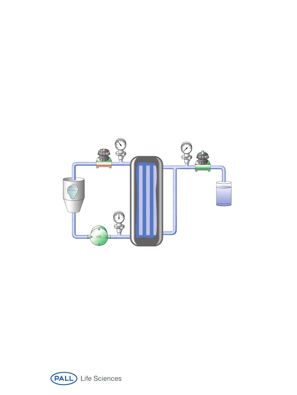
System hardware configurations vary, but should all have key components (Figure 2).
All TFF systems should have:
Feed/Retentate Flow Path
• Sample/feed tank
• Feed pump
• Feed and retentate pressure gauges or transducers
• Adjustable retentate valve
• Connecting piping
Permeate Flow Path
• Pressure gauge/transducer
• Valve
Figure 2
Typical TFF Hardware Setup
1.4.1 Options
In addition to the basic configuration, a valve on the feed side may be added to
isolate the system for integrity testing or to separate it from the feed tank. A flow
meter is also typically included with larger systems to allow feed or retentate flow rate
measurement. A second flow meter may be used on the permeate. Alternatively, the
permeate receptacle may be placed on a balance. The weight of permeate collected
can be used to calculate permeate volumes.
Temperature sensors may also be located at the feed tank, on the feed line after the
pump, and on the permeate line.
• Measuring temperature right after the pump will indicate if the pump is causing
excessive heating and possible denaturing of proteins.
• Measuring the temperature in the feed tank will only show gradual heating.
• Measuring the temperature of the permeate gives the actual temperature of
the fluid passing through the membrane for determining normalized water
permeability (NWP).
8
Retentate
Permeate
Feed
Tank
Waste
Feed
Pump
Rp
Pp
Fp
 Loading...