183
Aquarea air-to-water heat pumps - Planning and installation manual - 02/2022
Installation
6
6.8.2.3 Brief Overview of the external interfaces
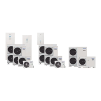
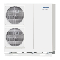
All in One unit, hydrokit and mono-bloc systems J or H Generation
Main PCB
2-way valve 3-way valve Optional
thermostat 1
Electric tank heater
H C N LC O N C O N
CN3
CN2CN1
CN4
CN5
CN6
1
2
3
4
1
2
3
4
1
2
3
4
1
2
3
4
5
6
1 12 23 34 45 6
Overload protection for
electric tank heater
External control
Operating unit
Bivalent heating source
Additional pumps
Room temperature
sensor heating circuit 1
Outdoor temperature
sensor
Tank temperature sensor
Optional PCB CZ-NS4P
Vcc
Bit1
Bit2
N O CN O CL N Cool Heat L N Cool Heat
CN206
CN205
CN203CN202CN201
CN204 CN207
CN208 CN209
CN210
1 1 1
11 1
1
1
1
1
2
2
2
2
3
3
3
3
4
4
4
4
5
6
2 2 2
22 2
3 3 3
33 3
4 4 4
44 4
5
55
6
66
Optional thermostat 2 Optional thermostat 1 Mixing valve 1 Mixing valve 2
External compressor
switch
Heating/ Cooling Switch
SG signal
Swimming pool pump
Solar station
Error signal
Pump for heating circuit 1
Pump for heating circuit 2
Room temperature
sensor for heating circ. 2
Water temperature
sensor for heating circ. 2
Water temperature
sensor for heating circ. 1
Demand control signal
Solar temperature sensor
Room temperature
sensor for heating circ. 1
Temperature sensor for
buffer tank
Temperature sensor for
swimming pool
 Loading...