44
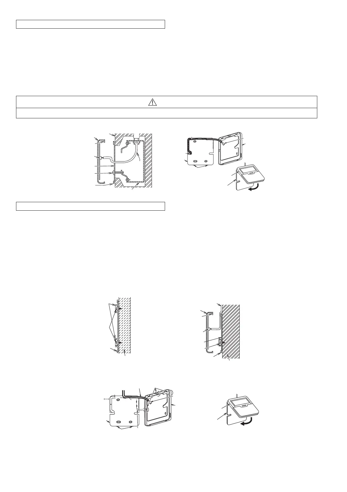
A. IF REMOTE CONTROLLER CABLE IS EMBEDDED
1 Embed an outlet box (JIS C 8336) into the wall. Outlet box maybe purchased separately. Medium size
square outlet box (obtain locally) Part No. DS3744 (Panasonic Co., Ltd.) or equivalent.
2 Secure the remote controller lower case to the outlet box with the two accessory screws 3. Make sure that
the lower case is flat againts the wall at this time, with no bending.
3 Pass the remote controller cable 2 into the box.
4 Route the remote controller cable 2 inside the lower case through rear feeding-out direction.
5 Insert firmly the connector of remote controller cable 2 to connector (CON1) in the upper case circuit board.
6 Secure the remote controller upper case to the lower case with the tabs provided.
CAUTION
When the wall is hollow, please be sure to use the sleeve for remote controller cable to prevent dangers caused by mice biting the cable.
Outlet box (JIS C 8336)
Wall
Upper case
Upper tab
Connector
(CON1)
Lower case
Screws
3
Lower tab
Remote
controller
cable
2
Remote controller cable
2
Rear feeding-
out position
Lower
case
Connector
(CON1)
Ta b s
Upper
case
Upper case
Lower case
B. IF REMOTE CONTROLLER CABLE IS EXPOSED
1 Install the remote controller lower case to the wall with the two accessory screws 4.
2 Fasten the screws properly until screw head is lower than the rib and reach the base of remote controller
lower case to ensure they do not damage the PCB inside the remote controller 1.
3 The feeding-out direction for the remote controller cable can be either via top, left or right side.
4 Use nipper to cut a notch at the upper case. (Select the intended feeding-out position)
5 Route the remote controller cable 2 inside the lower case in accordance with the intended feeding-out
direction. (Refer to the illustration at below).
6 Insert firmly the connector of remote controller cable 2 to connector (CON1) in the upper case circuit board.
(Refer to the illustration)
7 Secure the remote controller upper case to the lower case with the tabs provided.
Rib
Screws
4
Remote
controller
lower case
Wall
Wall
Remote controller cable
2
Upper case
Upper tab
Connector
(CON1)
Lower case
Screws
4
Lower tab
Upper
case
Lower
case
Connector
(CON1)
Upper
case
Tabs
Lower case
Right feeding-out position
Remote
controller
cable
2
Left feeding-
out position
Top feeding-out position
Notches
 Loading...