48
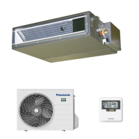
12.1.7.2 Connecting the Piping to Outdoor
Decide piping length and then cut by using pipe cutter. Remove burrs from cut edge. Make flare after inserting the
flare nut (locate at valve) onto the copper pipe. Align center of piping to valve and then tighten with torque wrench to
the specified torque as stated in the table.
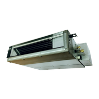
12.1.7.3 Connecting the Piping to Outdoor Multi
Decide piping length and then cut by using pipe cutter. Remove burrs from cut edge. Make flare after inserting the
flare nut (locate at valve) onto the copper pipe. Align center of piping to valve and then tighten with torque wrench to
the specified torque as stated in the table.
*
For Gas side piping please refer table and diagram below
Outdoor Multi Combination Model
R410A Model
Pipe size (refer
to diagram)
R32 Model
Pipe size (refer
to diagram)
CS-MZ20*
CS-Z25*
CS-Z35*
CU-2E12*
CU-2E15*
CU-2E18*
CU-3E18*
CU-3E23*
CU-4E23*
CU-4E27*
CU-5E34*
CU-2Z35*
CU-2Z41*
CU-2Z50*
CU-3Z52*
CU-3Z68*
CU-4Z68*
CU-4Z80*
CU-5Z90*
CS-Z50* CU-2E18*
CU-3E18*
CU-3E23*
CU-4E23*
CU-4E27*
CU-5E34*
(CZ-MA1P)
CU-2Z50*
CU-3Z52*
CU-3Z68*
CU-4Z68*
CU-4Z80*
CU-5Z90*
CS-Z60* CU-3E23*
CU-4E23*
CU-4E27*
CU-5E34*
(CZ-MA2P)
CU-3Z68*
CU-4Z68*
CU-4Z80*
CU-5Z90*
(CZ-MA2P)
*
Kindly contact authorized dealer for connectivity validity.
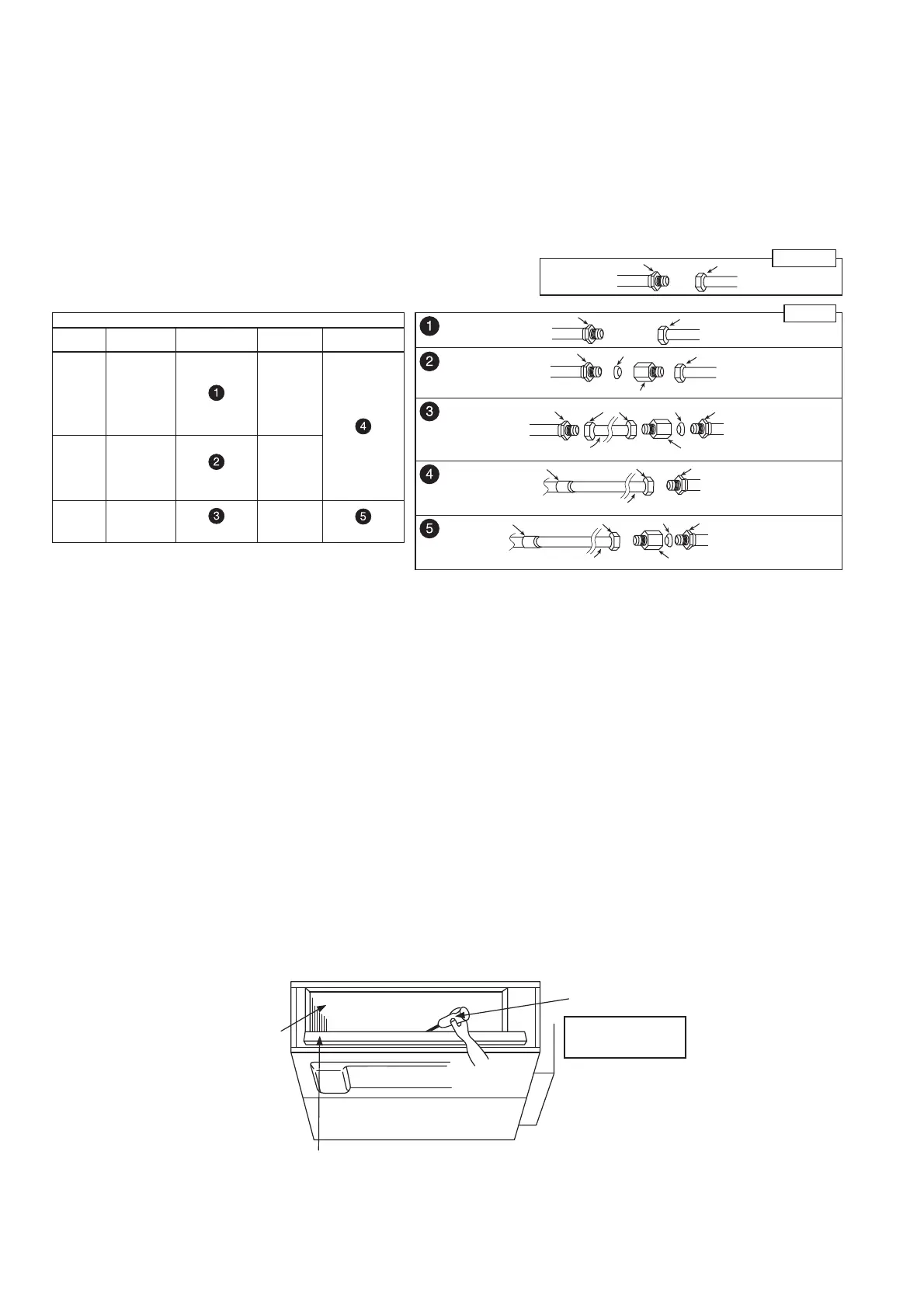
Connection pipe
(female side)
Auxiliary pipe
(male side)
Flare Nut
Hall Union
Liquid side
Connection pipe (female side)
Auxiliary pipe (male side)
Flare Nut
Hall Union
Hall Union
Packing
Connection pipe
(female side)
Auxiliary pipe
(male side)
Pipe size reducer (CZ-MA1P)
Flare Nut
Auxiliary pipe
(male side)
(Outdoor)
Auxiliary pipe
(male side)
(Indoor)
Hall Union
Hall Union
Packing
Connection pipe (female side)
Pipe size expander (CZ-MA2P)
Flare Nut
Auxiliary pipe
(male side)
(Outdoor)
(Indoor)
Hall Union
Brazing point
Connection pipe (female side)
Flare Nut
Auxiliary pipe (male side)
(Outdoor)
(Indoor)
Hall Union
Brazing point
Connection pipe (female side)
Flare Nut
Packing
Pipe size expander (CZ-MA2P)
Gas side
12.1.8 Switching the High State Switch (SW2)
To increase the air volume, open the control box and on the control board, switch the FAN switch (SW2) to “HI”.
See the diagram for “Connecting the Indoor/Outdoor Connection Cable”.
12.1.9 Note: Enabling long-range remote control
To maintain EMC emission limits, cabling interconnecting the HA terminal and subsequent opto-coupler, must be
no more than 1.9 m length.
Loop four turns of this cable through a suitable small EMC ferrite toroid, and protect with a short length of large
diameter heat-shrink tube.
There is no similar length limit for cable following on from the opto-coupler isolation.
12.1.10 Check the Drainage
Check after connecting the power supply.
Pour approximately 600 cc of water into the drain pan of the main unit using a squeeze bottle, etc.
Press the drain test run switch on the control board in the control box to start the drain motor and check whether
the water drains normally.
(The drain motor operates for approximately 5 minutes and then stops automatically.)
(See the diagram for “Connecting the Indoor/Outdoor Connection Cable”.)
Heat
exchanger
Drain pan
Squeeze bottle
Approximately
600 cc of water
 Loading...