50
8 Mount valve caps onto the 2-way valve and the 3-way valve.
o Be sure to check for gas leakage.
If gauge needle does not move from 0 cmHg (0 MPa) to -76 cmHg (-0.1 MPa), in step 3 above take the
following measure:
- If the leak stops when the piping connections are tightened further, continue working from step 3.
- If the leak does not stop when the connections are retightened, repair location of leak.
- Do not release refrigerant during piping work for installation and reinstallation.
- Take care of the liquid refrigerant, it may cause frostbite.
12.2.5 Connect the Cable to the Outdoor Unit
(FOR DETAIL REFER TO WIRING DIAGRAM AT UNIT)
1 Remove the control board cover from the unit by loosening the screw.
2 Cable connection to the power supply through Isolating Devices (Disconnecting means).
o Connect the approved polychloroprene sheathed power supply cord 3 x 1.5 mm
2
(1.0 ~ 1.5HP) or 3 x
2.5 mm
2
(2.0 ~ 2.25HP), type designation 60245 IEC 57 or heavier cord to the terminal board, and
connect the other end of the cable to Isolating Devices (Disconnecting means).
o Do not use joint power supply cord. Replace the wire if the existing wire (from concealed wiring, or
otherwise) is too short.
o In unavoidable case, joining of power supply cord between isolating devices and terminal board of air
conditioner shall be done by using approved socket and plug rated 15/16A (1.0 ~ 1.5HP) or 16A (2.0 ~
2.25HP). Wiring work to both socket and plug must follow to national wiring standard.
3 Connection cable between indoor unit and outdoor unit shall be approved polychloroprene sheathed 4 x
1.5 mm
2
flexible cord, type designation 60245 IEC 57 or heavier cord. Allowable connection cable length of
each indoor unit shall be 30 m or less.
4 Demand control signal transmission cable between outdoor unit and DRED (Demand response enabling
devices) shall be double insulation layer, polychloroprene sheathed (>50V) or type destination AS/NZS
50000.2 with size 4 x (0.5 mm
2
to 2.0 mm
2
) cable, where the maximum allowable length is 30 m.
5 Connect the power supply cord and connection cable between indoor unit and outdoor unit according to the
diagram below.
6 Secure the power supply cord and connection cable onto the control board with the holder.
7 Attach the control board cover back to the original position with screw.
8 For wire stripping and connection requirement, refer to instruction 12.1.5 of indoor unit.
Note: Isolating Devices (Disconnecting means) should have minimum 3.0 mm contact gap.
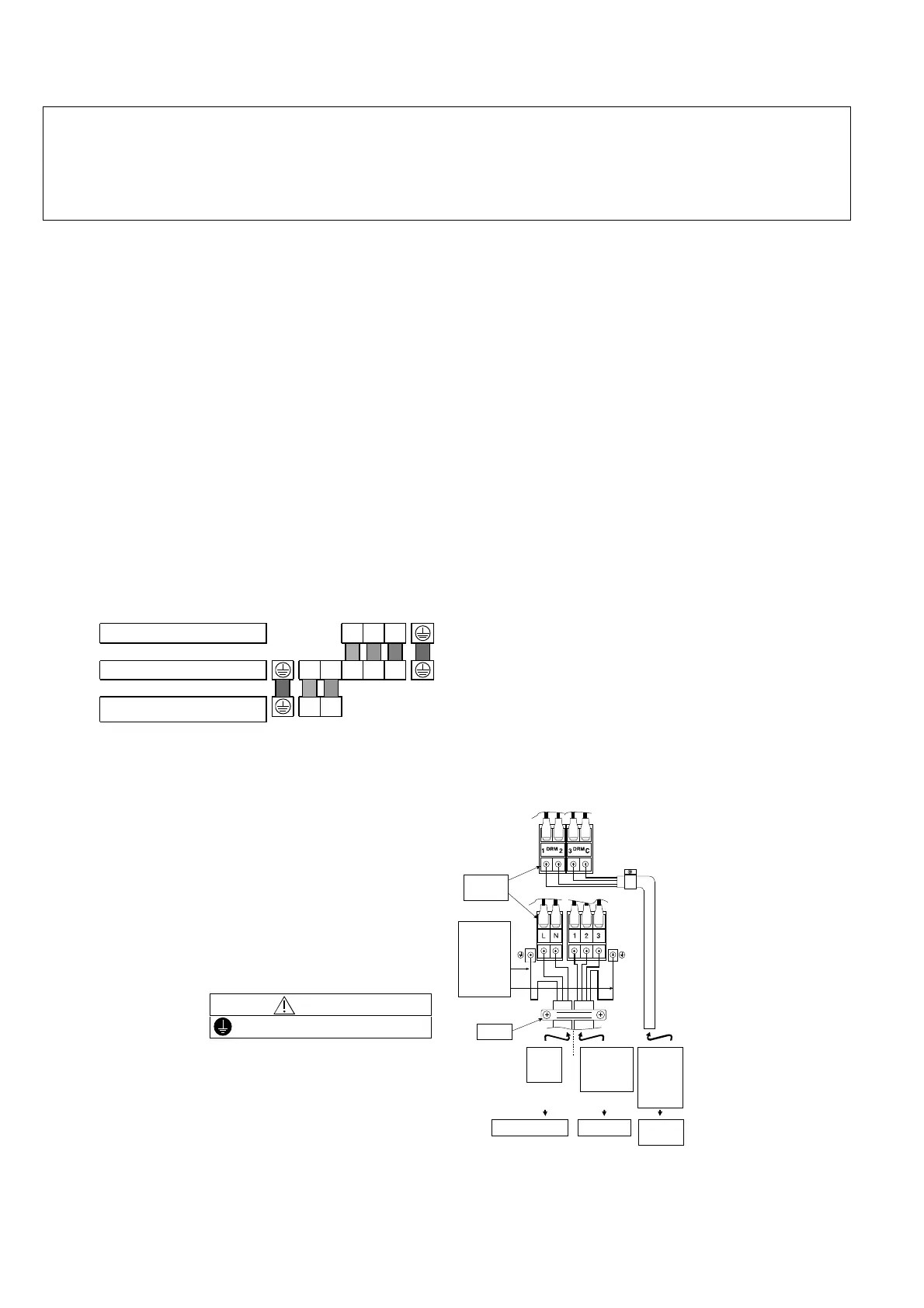
Earth wire shall be Yellow/Green (Y/G) in colour and longer than other AC wires for safety reason.
321tinuroodniehtnoslanimreT
Colour of wires (connection cable)
Terminals on the outdoor unit LN123
(Power supply cord)
Terminals on the isolating devices
(Disconnecting means)
(L) (N)
WARNING
This equipment must be properly earthed.
Earth Wire
longer
than
others
AC wires
for safety
reason
DRED
(Demand
response
enabling
devices)
Terminal
Board
Holder
Indoor &
outdoor
Connection
cable
Indoor unitIsolating Devices
Power
supply
cord
Remote
Agent

 Loading...