- 11 -
Disassembly for Service
Back Cover
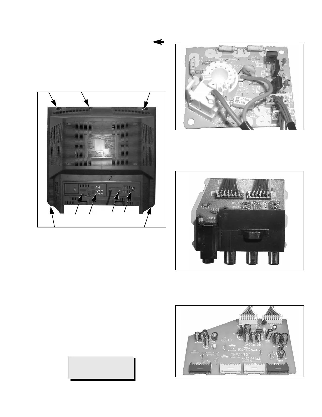
Remove all the screws marked with an arrow( )
from the back of the Receiver.
• 3 screws at the top edge of the Receiver.
• 1 screw at each lower corner of the Receiver.
• 1 screw by the A/V jacks.
• 1 screw by the AC cable opening cover.
• 1 screw closest to the antenna terminal.
• 1 screw by the Fly-back assembly.
Figure 5. Back Cover Screw Location
A-Board - Main Chassis
The board is secured in place by the guide rails and by
the DVD bracket. See Fig. 14 on page 14.
1. The A-board is mounted in guides (rails) which are
attached to the DVD bracket and lock to the
cabinet. To remove the rails, DVD bracket and
A-Board press on the release tabs located at the
bottom of the cabinet, behind the rails and pull
forward.
2. Release cable connectors leading to the A-Board
and also from clampers.
3. Press on the tabs located at the front end of the
A-Board and slide the board forward.
Note: Some tie-wraps that secure the wire dressings
may need to be unfastened for chassis
removal.
C-Board - CRT Output
Socket plugs onto the CRT neck.
Figure 6. C-Board Assembly
G-Board - Video Input (Front)
Fastened to the front panel. Position bottom of
board on back of front panel and secure with
1 screw.
Figure 7. G-Board Assembly
JJ-Board - A/V Switch, A/V Decoder
Plugs perpendicularly into 4 connectors on the
A-Board.
Figure 8. JJ-Board Assembly
IMPORTANT NOTE:
Reuse hardware (screws,
bolts, connectors, etc.) upon
reassembling the Receiver.



 To Next Page