HGFEDCBA
1
2
3
4
5
CT-27DC50B
MTNC000522C1
Side B
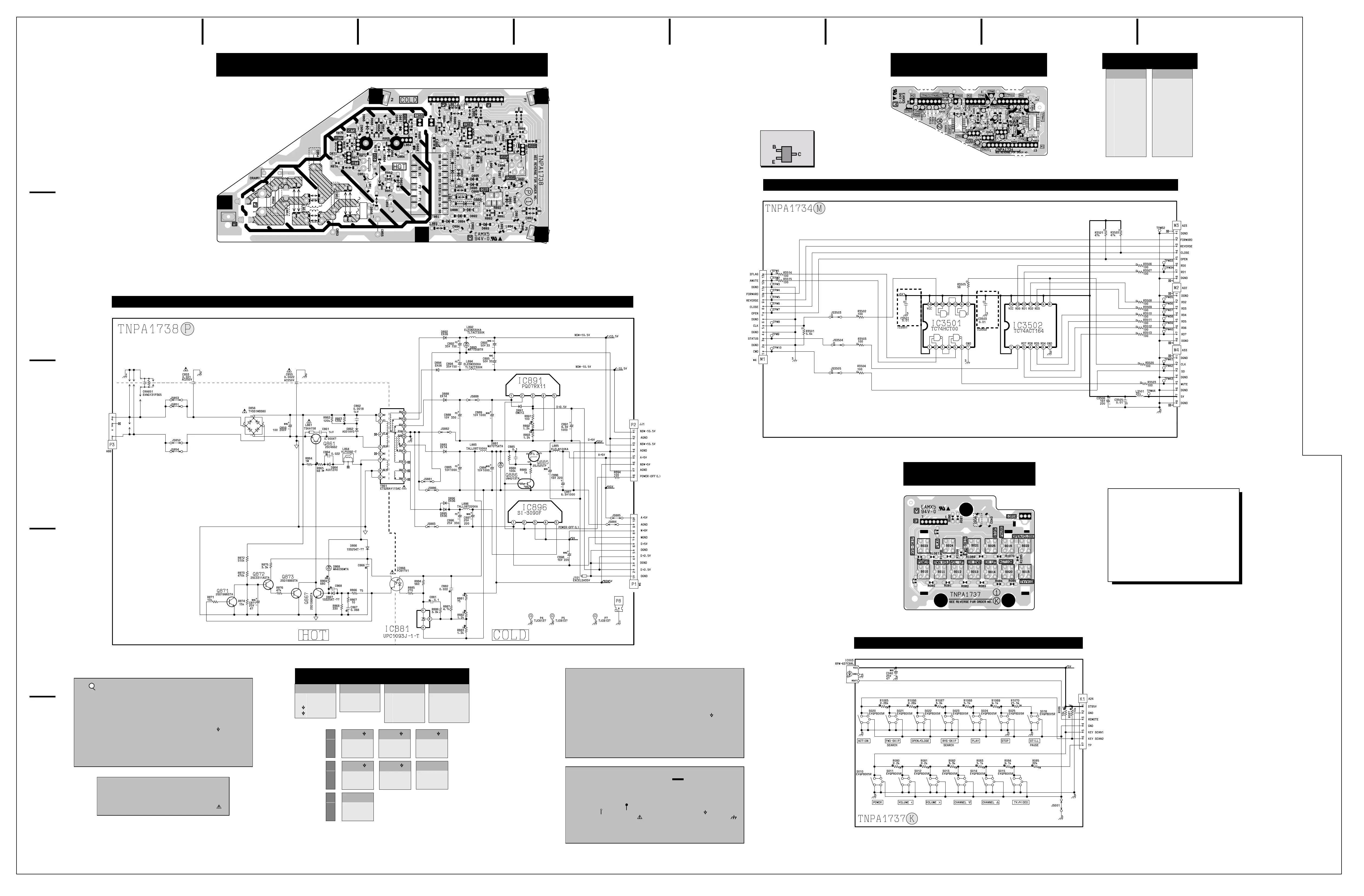
K, M & P-Board Schematics &
Layouts; M & P-Board Voltages
Sheet 2 of 3
P-Board Layout
TNPA1738
P-Board Schematic
M-Board Layout
TNPA1734
M-Board Schematic
K-Board Layout
TNPA1737
K-Board Schematic
IC3502
1
2
3
4
5
6
7
8
9
10
11
12
13
14
. . . . . 4.96
. . . . . 2.47
. . . . . 1.00
. . . . . 2.00
. . . . . 0.74
. . . . . 0.85
. . . . . GND
. . . . . 4.17
. . . . . 4.95
. . . . . 0.87
. . . . . 1.82
. . . . . 0.93
. . . . . 2.07
. . . . . 4.95
M-Board Voltages
IC3501
1
2
3
4
5
6
7
8
9
10
11
12
13
14
. . . . . .4.96
. . . . . .3.27
. . . . . .0.00
. . . . . .0.00
. . . . . .0.22
. . . . . .4.95
. . . . . GND
. . . . . .4.17
. . . . . .4.96
. . . . . .0.79
. . . . . .0.79
. . . . . .4.96
. . . . . .2.69
. . . . . .4.95
B
C
E
Q861
0.00
136.00
GND
IC866
1
2
3
4
. . . . . 5.16
. . . . . 4.03
. . . . 58.00
. . . . 64.00
IC881
A
R
K
. . . . . GND
. . . . . 2.49
. . . . . 2.84
IC891
1
2
3
4
5
. . . . . 4.00
. . . . . 0.00
. . . . . 0.00
. . . . . 0.00
. . . . . GND
B
C
E
Q886
0.00
5.10
GND
G
D
S
Q885
5.11
0.71
5.16
IC896
1
2
3
4
5
. . . . . GND
. . . . . 0.00
. . . . . 0.00
. . . . . 0.00
. . . . . 9.41
Q867
.50
0.00
GND
Q871
.62
0.00
GND
Q872
0.00
7.26
0.00
Q873
0.00
0.00
GND
P-Board Voltages
CHIP TRANSISTOR
LEAD DESIGNATION
Notes:
The above boards have been
modified to enhance and display
traces otherwise hidden by a mask.
Check Parts List for most recent
component values and part numbers.
Obtain voltages with a digital
multimeter.
IMPORTANT SAFETY NOTICE
THIS SCHEMATIC DIAGRAM INCORPORATES SPECIAL FEATURES
THAT ARE IMPORTANT FOR PROTECTION FROM X-RADIATION, FIRE
AND ELECTRICAL SHOCK HAZARDS. WHEN SERVICING IT IS
ESSENTIAL THAT ONLY MANUFACTURERS SPECIFIED PARTS BE
USED FOR THE CRITICAL COMPONENTS DESIGNATED WITH A IN
THE SCHEMATIC.
Waveform Measurements
1. indicates waveform measurement.
(Measurement can be taken at the
best accessible location in common
to the indicated point.)
2. Taken with an NTSC signal
generator connected to the antenna
terminal. (NTSC color bar pattern of
8 bars of EIA colors, 100 IRE white
and 7.5 IRE black.)
3. Customer Controls (Picture/Audio
Menu) are set to Normalize. Volume
is set to “MIN”.
4. All video and color waveforms are
taken with a wideband scope and
a probe with low capacitance (10
to 1). Shape and peak altitudes
may vary depending on the type
of Oscilloscope used and its
settings.
5. Ground symbol shown on
waveform number indicates (Hot)
ground lead connection of the
Oscilloscope.
CAUTION: Incorrect ground
connection of the test equipment will
result in erroneous readings.
3
Schematic Notes
1. Resistors are carbon 1/4W unless
noted otherwise.
2. Capacitors are ceramic 50V unless
noted otherwise.
3. Coil value notes is inductance in µH.
4. Test point indicated by ; Test point
but no pin .
5. Components indicated with are
critical parts and replacement should
be made with manufacture specified
replacement parts only.
6. (BOLD LINE) indicates
the route of B+ supply.
7. The schematic diagrams are
current at the time of printing and
are subject to change without
notice.
8. Ground symbol indicates HOT
GROUND CONNECTION;
indicates COLD GROUND.
NOTE: All other component symbols
are used for engineering
design purposes.
Voltage Measurements
1. Voltage measurement:
- AC input to the Receiver is 120V.
NTSC (HD, 1125i & 525P when
applicable) signal generator is
connected to the antenna of the
Receiver. (Color bar pattern of
100 IRE white and 7.5 IRE black.)
- All Picture and Audio adjustments
are set to Normalize.
TV ANT/CABLE - (Set-Up Menu)
in TV/ANT Mode
Volume - Min.
TV/Video SW - TV position
Audio Mode - Stereo
- Voltage readings are nominal
and may vary ±10% on active
devices. Some voltage
reading will vary with signal
strength and picture content.
- Supply voltages are nominal.
2. Ground symbol indicates
ground lead connection of meter.
Incorrect ground connection will
result in erroneous readings.
CAUTION: Incorrect ground
connection of the test equipment
will result in erroneous readings.
Boards Designation
• A-Board - Main Chassis
• C-Board - CRT Drive
• G-Board - Front Video Input
• JJ-Board - A/V Amp Interface
• K-Board - Customer Controls
• M-Board - DVD-TV CPU Interface
• P-Board - DVD Power Supply
• W-Board - DVD Unit Interface
 Loading...