VQT2J45
9
STEP 1
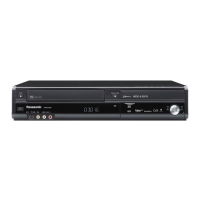
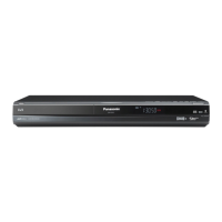
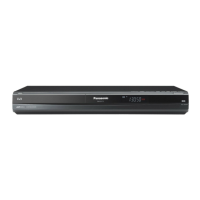
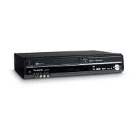
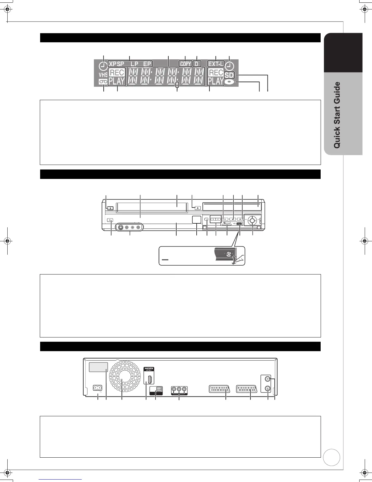
The Unit’s Display
1 Timer recording indicator .......................... (> 23)
On:
When a timer recording programme is registered and a
record able disc or video cassette is inserted.
Flashes:
When the unit cannot record a timer recording programme
(e.g., there is no disc or video cassette, etc.).
2 Recording mode indicator
3 Main display section
Current time/playback counter, various messages
4 Copying indicator
5 Digital broadcast indicator
Lights when the unit is receiving digital broadcast.
6 Linked timer recordings with external
equipment indicator.................................... (> 30)
7 Tape indicator
8 Recording/Playback indicator
9 Remote control visual feedback
This flashes when it is operated by the remote control.
: Disc indicator
This indicator lights up when a disc is inserted.
; SD card slot indicator
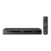
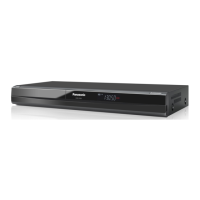
Main Unit
1 Cassette eject button ................................. (> 89)
2 Disc tray open/close button ...................... (> 20)
3 Start recording button ............................... (> 22)
4 Stop button ......................................... (> 20, 22)
5 Play/a1.3 button....................................... (> 20)
6
Standby/on switch (Í/I) ..................... (> 13)
Press to switch the unit from on to standby mode
or vice versa. In standby mode, the unit is still
consuming a small amount of power.
7 AV3 input terminals.................................... (> 31)
8 DVD/VHS drive indicator ........................... (> 20)
≥Lights when the DVD or VHS drive is selected.
≥There is no drive indicator for HDD or SD drive.
9 DRIVE SELECT button.................. (> 20, 22, 42)
≥Drive changes each time you press [DRIVE SELECT].
: Channel Select button ........................ (> 19, 22)
; SD card slot ............................................... (> 89)
< USB port ................................................... (> 89)
= One Touch Copying operation button ........ (> 24)
≥From VHS to HDD or DVD
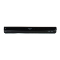
Rear Panel
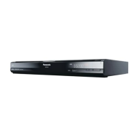
1 AC IN~ = Power supply ............................ (> 11)
Connection for the AC mains lead
2 Serial number
3 Cooling fan
4 HDMI AV OUT terminal....................... (> 12, 88)
Digital audio and video output terminal
5 Digital audio output terminal ...................... (> 87)
6 AUDIO/VIDEO output terminals ............... (> 87)
7 AV2 (EXT) 21-pin Scart terminal.......... (> 11, 86)
Connection of an external unit
8 AV1 (TV) 21-pin Scart terminal ..... (> 10, 11, 86)
TV set connection
9 Aerial output terminal.................... (> 10, 11, 86)
: Aerial input terminal...................... (> 10, 11, 86)
AV3 IN
DRIVE SELECT
REC
CH
OPEN/CLOSE
EJECT
COPYING
VHS
DVD
DVD
VHS
VHS
SD CARD
S VIDEO
VIDEO
L/MONO
AUDIO
R
HDD
Opening the front panel
Press down on the
part with your finger.
The unit‘s display
Remote Control
signal sensor
(> 7)
Cassette
compartment
Disc Tray
AC I N
RF
IN
RF
OUT
OPTICAL
DIGITAL AUDIO OUT
(PCM/BITSTREAM)
OUT
VIDEO
AV2 (EXT) AV1 (TV)
R-AUDIO
DMR-EX99V
Model No.
VR7AA01002 R
SER NO.
-L
DMR-EX99VEB_VQT2J45.book 9 ページ 2010年1月6日 水曜日 午前11時27分
 Loading...